三跨87m+130m+87m金山大桥设计(含CAD图)(论文计算书12900字,CAD图6张)
摘要
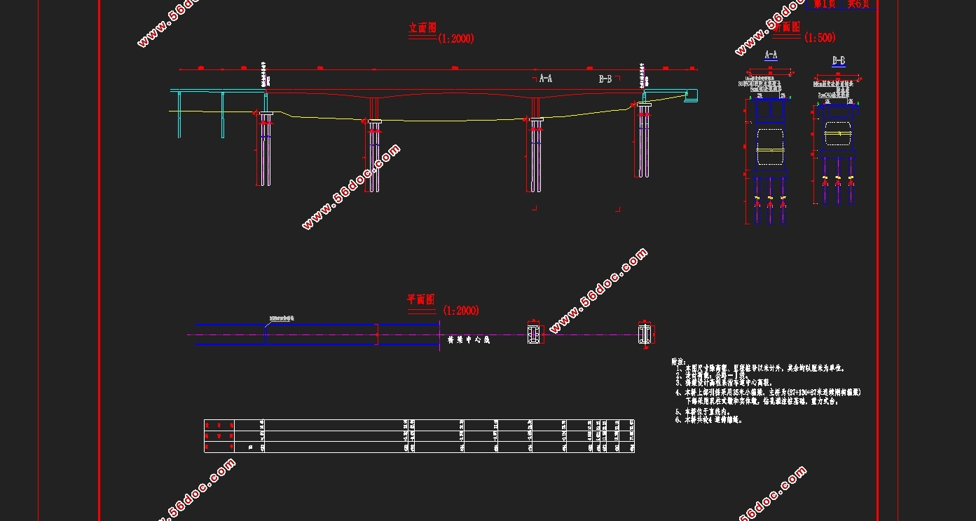
桥梁总长864m,其中主桥304m,为预应力混凝土连续刚构桥,共三跨,由87m+130m+87m组成,柔性墩,主梁截面形式为单箱双室。设计汽车荷载标准为公路1级。主梁采用挂篮悬臂对称浇筑。连续刚构桥最大的特点是梁墩固结,不仅拥有连续梁的特点,还包括无需支座,墩与基础的工程量少,结构的受力性能更加优越等优点。
本设计参考了国内外工程实例,对桥梁构造进行了学习和研究。由于桥宽18米,超过10米,故拟订主梁截面采用单箱双室截面,梁高按2次抛物线变化,桥墩处梁高8米,跨中3米。顶板厚度均取0.2m,底板厚度由桥墩处向跨中减小,桥墩处底板厚度为0.8m,跨中为0.25m。在设计中运用MIDAS建模内力分析,根据规范及EXCEL预估截面预应力钢束数量并进行钢筋的布置,然后进行荷载组合,得出荷载组合效应下的计算结果以及图示,最后通过Midas进行截面验算。图纸绘制包括桥梁方案设计图,控制截面布筋图,施工程序图,此外还翻译了相关外文。最后进行说明书的编撰以及各种资料的整理。
【关键词】: 预应力混凝土连续刚构桥;悬臂施工;内力分析;
Abstract
The total length of the bridge is 864m, of which the main bridge is 304m, which is a stressed concrete continuous rigid frame bridge, which consists of 87m + 130m + 87m. The flexible pier and main section are single box double chamber. Design the car load standard for highway level 1. The main beam is cantilevered with hanging basket symmetrical pouring. The main feature of the continuous rigid frame bridge is the consolidation of the beam pier, not only has the characteristics of continuous beam, but also includes the need for bearing, pier and foundation of the project less, the structure of the force performance is more superior and so on.
This design refers to the domestic and foreign engineering examples, the bridge structure of the study and research. As the bridge width of 18 meters, more than 10 meters, so the preparation of the main section of the main section of the use of single-box double-room section, the beam by 2 parabolic changes, pier pier 8 meters high, 3 meters across. The thickness of the roof is 0.2m, the thickness of the bottom plate is reduced from the pier to the span, the thickness of the bottom of the pier is 0.8m, and the thickness is 0.25m. In the design, the internal force analysis of MIDAS model is used to estimate the number of prestressed steel beams in the section according to the specification and EXCEL, and then the load combination is carried out. The results of the load combination and the results are shown. Finally, Cross section checking. Drawing drawings include bridge design drawings, control cross-section bar graphs, construction plans, in addition to translation of the relevant foreign language. Finally, the compilation of the instructions and the various information.
Key words: prestressed concrete continuous rigid frame bridge; cantilever construction; internal force analysis;
目 录
第一章 绪 论 1
1.1目的和意义 1
1.2方案比选 1
第二章 初步拟定 4
2.1 设计概述 4
2.2 截面尺寸拟定 4
2.2.1 变截面箱梁形式 4
2.2.2 主梁高度 4
2.2.3 顶底板厚度 4
2.2.4腹板厚度 5
2.2.5梗腋(承托) 5
2.3 主梁分段与施工节段划分 6
2.3.1 悬臂施工节段划分 6
2.3.2 施工阶段划分 6
第三章 主梁内力计算 7
3.1 桥梁电算 7
3.1.1 计算图式 8
3.1.2 施工阶段设计 8
3.2 MIDAS/CIVIL2012参数信息 9
3.2.1 材料特性 10
3.2.2 荷载信息 11
3.3恒载内力计算 11
3.3.1 毛截面几何特性 12
3.2.2 恒载内力计算 12
3.4活载内力计算 15
3.4.1横向分布系数的考虑 15
3.4.2活载因子的计算 15
3.5恒载与活载的内力组合计算 15
3.5.1承载能力极限状态 15
3.5.2正常使用极限状态 18
第四章 预应力钢束的估算与布置 21
4.1 预应力钢束的估算 21
4.2按承载能力极限计算 21
4.3按正常使用极限状态计算 22
4.4 预应力钢束估算结果 24
4.5 纵向预应力钢束的布置 24
第五章 截面验算 25
5.1 内力组合 25
5.2 截面验算 22
5.2.1 承载能力极限状态验算 23
5.2.2 正常使用极限状态验算 28
5.3构件的应力验算 34
5.3.1 使用阶段正截面压应力验算 36
5.3.2 使用阶段斜截面主压应力验算 36
5.3.3 施工阶段正截面法向应力验算 37
5.3.4 受拉区钢筋的拉应力验算 39
第六章 施工组织设计 42
6.1准备工作 42
6.2上部结构施工 42
6.3 下部结构施工 42
6.4 施工进度安排 42
总结 44
致 谢 45
参考文献 46
|
