徐州市某县给水工程设计(含CAD图)(任务书,开题报告,计算说明书17000字,CAD图9张)
摘要
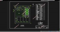
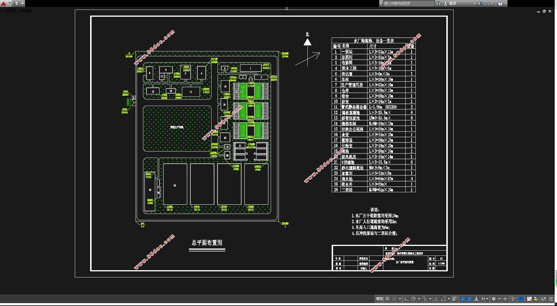
该设计为徐州市某县给水工程设计,分为给水管网设计和给水厂设计。给水管网设计用水量为40.881万吨,供水量大,范围广。水厂所在地高程约为34.80米,供水部分地区高程达51.80米,由此水厂出厂压力67.8米。考虑远期规划,管网设计一期完成,水厂工艺二期完成,此设计为一期管网与水厂工艺设计。水厂位于小沿河边,就近取水。处理水质达Ⅲ类标准,污染物较少,考虑水厂自用水,水厂实际生产水量为21.5万吨。水厂处理选择常规工艺:絮凝选择回旋式隔板絮凝池,共6座;沉淀选择斜管沉淀池,共6座;过滤选择V型滤池,共6座;消毒选择液氯消毒,设加氯间;清水池设4座。絮凝池与斜管沉淀池合建,二泵房与反冲洗泵房合建。厂区实行雨污合流后排入市政污水管道,水厂工艺废水如絮凝沉淀池排泥水和V型滤池反冲洗水,由于所含泥沙较多但污染不重,另设一条排水管排至小沿河取水口下游。
关键词:给水工程、管网设计、水厂设计
Abstract
This is the water supply engineering of Tongshan County, Xuzhou City, the engineering divided into the water pipe network design and the waterworks design. The water design consumption is 408810 tons, which is large and wide in the range.The elevation of waterworks is about 34.80 meters, when some of the other areas are about 51.80 meters, so the waterworks pressure is 67.8m. Considering the long- term planning, the water pipe design will be finished in one phases, and the waterworks design will be finished in two phases.This design is the one phase of water pipe network and the waterworks. The waterworks is located in the Xiaoyan River, draw water nearby. Xiaoyan water got a Ⅲclass quality standards with few pollutant. Considering the supply of waterworks, it`s actual production is 215000 tons. Water treatment process selection: six spiral baffled flocculation tanks, six inclined tube sedimentation tanks, six V type filters, disinfected by chlorination and set a chlorination room, and four clear water tanks. Spiral baffled flocculation tanks are built with inclined tube sedimentation tanks, two pumping station is built with the backwash pumping station. The implementation of rainwater and sewage discharged into the municipal sewage pipe, waterworks wastewater such as the sludge of flocculation tanks and the backwash water of filters and sedimentation, due to it`s lot`s of sediment and few pollution, they will adrain to the downstream of the water intake in Xiaoyan river.
Keyword:water supply engineering,water pipe network design,waterworks design
目录
摘要 1
Abstract 2
第一章 给水管网设计与计算 7
1.1设计用水量及其调节计算 7
1.1.1最高日设计用水量 7
1.1.2设计用水量变化及其调节计算 9
1.1.3供水泵站供水流量确定 9
1.2设计流量分配与管径设计 10
1.2.1节点流量分配计算 10
1.2.2管段设计流量分配 11
1.2.3管段长度确定 12
1.2.4管径及流速确定 12
1.2.5设计工况分析 13
1.3泵站扬程设计 15
1.4管网设计校核 15
1.4.1事故工况校核 15
1.4.2消防工况校核 16
1.4.3最终成果图 19
第二章 絮凝池设计与计算 21
2.1 混凝设施 21
2.1.1 溶液池容积 21
2.1.2 溶解池容积 21
2.1.3 投药管 22
2.1.4 溶解池搅拌设备 22
2.1.5 计量投加设备 22
2.1.6 药剂仓库 23
2.2 混合设备设计计算 23
2.2.1 设计管径 23
2.2.2 混合单元数 23
2.2.3 混合时间 24
2.2.4 水头损失 24
2.2.5 校核GT值 24
2.3 回旋式隔板絮凝池设计计算 24
2.3.1 设计计算 24
第三章 斜管沉淀池设计与计算 29
3.1 设计计算 29
3.1.1 沉淀池尺寸计算 29
3.1.2 沉淀池的进水设计 30
3.1.3沉淀池集水系统设计 31
3.1.4沉淀池排泥系统设计 33
3.1.5斜管沉淀池计算结果和草图 33
3.1.6配水井 34
第四章V型滤池 35
4.1 设计计算 35
4.1.1池体计算 35
4.1.2 反冲洗管渠系统 37
4.1.3滤池管渠的布置 40
4.1.4 V型槽设计 43
4.1.5冲洗水泵扬程 44
4.2鼓风机 48
4.2.1鼓风机选型 48
4.2.2鼓风机房尺寸 49
4.3反冲洗泵房 49
第五章 消毒 50
5.1 加氯量计算 50
5.2 储氯量计算 50
第六章 清水池设计 51
6.1 清水池的有效容积 51
6.1.1调节容量 51
6.1.2自用水调节储量 51
6.1.3消防储量 51
6.1.4安全储量 51
6.1.5清水池有效容积 51
6.1.6清水池尺寸的确定 51
6.2管道布置 52
6.2.1进水管设计 52
6.2.2出水管设计 52
6.2.3排水管设计 53
6.2.4溢流设计 53
6.3 清水池的布置 54
6.3.1 导流墙 54
6.3.2 检修孔 54
6.3.3通气设计 54
6.3.4 覆土厚度 54
6.4清水池标高 55
第七章 吸水井设计 55
7.1 吸水井布置要求 55
7.2 吸水井尺寸计算 56
7.2.1吸水喇叭口直径 56
7.2.2吸水喇叭口的最小悬空高度(喇叭口与井底间距) 57
7.2.3喇叭口间距 57
7.2.4吸水喇叭口最小淹没水深 58
7.2.5吸水井进水长度 58
第八章 二级泵房设计 58
8.1 设计资料 58
8.1.1 设计水量 59
8.1.2 管网设计 59
8.2 二级泵站设计要点 59
8.3 设计扬程 59
8.4 水泵和电机的选择 60
8.4.1水泵的选择 60
8.5 二级泵站泵房尺寸设计 61
8.5.1 机组布置和基础计算 61
8.5.2 吸水和压水管路设计 62
8.5.3 泵房平面尺寸的确定 63
8.5.4 复核水泵电机 63
8.5.5 泵机组的标高 65
8.5.6 附属设备的选择 67
8.5.7 泵房高度计算 68
第九章 水厂高程设计计算 69
9.1各构筑物之间连接管道的水头损失计算 69
9.1.1清水池到吸水井 69
9.1.2 V型滤池到清水池 69
9.1.3沉淀池到V型滤池 69
9.2 各净水构筑物的水头损失 70
9.3 各构筑物的水面标高 70
第十章 一级泵房设计 71
10.1取水构筑物形式 71
10.2设计计算 71
10.2.1 设计取水量 71
10.2.2 河流水位 71
10.2.3 进水孔要求 71
10.2.4 设计计算 71
10.2.5 进水间和吸水室的设计 73
10.3 起吊设备 73
10.3.1 格网起吊设备 73
10.3.2 格网起吊设计计算 74
10.4 进水室吸水室平面尺寸 74
10.5设计扬程 74
10.6 水泵机组的选择 75
10.7 吸水管路与压水管路计算 76
10.8 机组及泵房标高 76
10.9 吸水管和压水管路中损失的计算 77
10.9.1吸水管路中的损失 77
10.9.2压水管路损失 77
10.10 附属设备 78
10.10.1排水设备 78
10.10.2通风设备 78
10.10.3起重设备 78
10.11 泵房高度 78
参考文献 80
谢辞 81
|