北斗导航终端接收天线设计(论文11000字)
摘要:随着近年来无线通信技术的快速发展,卫星导航技术广泛应用于生产生活和军用国防事业上,对现代经济的发展起到了极大的推动作用。我国的卫星导航事业发展较晚,但是发展速度很快,北斗卫星导航定位系统已经实现了全球定位,使中国成为美国和俄罗斯后第三个能够建立成熟卫星导航系统的国家,所以北斗导航终端天线的设计具有重大意义。北斗系统运行在L频段与S频段,极化方式为圆极化。本文以北斗卫星导航接收终端作为研究对象,设计终端接收天线,利用HFSS电磁仿真软件研究了正馈、偏馈矩形微带天线,并进行了优化,并通过开槽的方式对圆极化参数进行进一步的优化设计:依据天线中心频率、极化方式及介电板的介电常数等通过理论经验公式计算确定天线的大概形式,利用HFSSS软件对天线的增益、带宽、旁瓣、极化轴比、电压驻波比等指标进行仿真分析。根据仿真结果对天线的馈电结构和特性参数进行优化设计,得到天线最优的几何结构及尺寸参数,使得优化后的右旋圆极化天线的电性能参数能更好的满足所要求的技术指标,最后在微波暗室对天线性能指标进行测量,并查找检查未达到要求的指标,然后改进天线,重复设计过程,设计得到一个用于北斗终端接收的右旋圆极化天线。
关键词:北斗导航系统;右旋圆极化;宽带宽;矩形微带;HFSS
Design of receiving antenna for BeiDou navigation terminal
Absrtact: With the rapid development of wireless communication technology in recent years, satellite navigation technology has been widely used in production, life and military defense, which has played a great role in promoting the development of modern economy.China's satellite navigation industry develops late, but it develops rapidly. Beidou Satellite Navigation and Positioning System has achieved global positioning, making China the third country after the United States and Russia to establish a mature satellite navigation system. Therefore, the design of Beidou Navigation Terminal Antenna is of great significance. Beidou system runs in L band and S band, and its polarization mode is circular polarization. n this paper, the Beidou satellite navigation receiving terminal is taken as the research object. The terminal receiving antenna is designed. The forward-fed and biased-fed rectangular microstrip antenna is studied and optimized by using HFSS electromagnetic simulation software. The circular polarization parameters are further optimized by slotting: the approximate form of the antenna is determined by theoretical empirical formulas based on the antenna central frequency, polarization mode and dielectric constant of dielectric plate, and the gain, bandwidth, sidelobe, polarization axis ratio and voltage standing wave ratio of the antenna are simulated and analyzed by HFSSS software. According to the simulation results, the feed structure and characteristic parameters of the antenna are optimized, and the optimal geometric structure and size parameters of the antenna are obtained, so that the electrical performance parameters of the optimized right-handed circularly polarized antenna can better meet the required technical specifications. Finally, the antenna performance indexes are measured in the microwave anechoic chamber, and the indexes that fail to meet the requirements are found and checked, and then the antenna is improved. A right-handed circularly polarized antenna for Beidou terminal reception is designed by repeating the design process.
Key words: Beidou navigation system; right-handed circular polarization; wide bandwidth; rectangular microstrip; HFSS
目 录
1绪论 1
1.1研究背景 1
1.1.1卫星导航系统发展概述 1
1.1.2中国北斗卫星导航系统 2
1.2发展现状 2
1.3研究意义 3
1.4论文安排 3
2天线基础理论 4
2.1天线性能参数 4
2.1.1方向图 4
2.1.2增益 4
2.1.3输入阻抗 4
2.1.4天线的极化 4
2.2接收天线理论 5
3微带天线设计原理 6
3.1结构形式 6
3.2辐射原理 6
3.3馈电方式 6
3.3.1微带线馈电 6
3.3.2同轴馈电 7
3.3.3 馈点选择 7
3.4矩形微带天线 7
3.4.1特性参数 7
3.4.2 圆极化方式 8
3.5 HFSS仿真软件 9
3.5.1 HFSS软件介绍……....................................................................................................…9
3.5.2 HFSS天线设计流程……............................................................................................…9
4 北斗导航终端微带天线的设计 10
4.1设计目标 10
4.2正馈矩形微带天线设计 10
4.2.1天线结构……...........................................................................................................…10
4.2.2初始设置……...........................................................................................................…10
4.2.3仿真及优化….......................................................................................................……10
4.3偏馈矩形微带天线设计 12
4.3.1天线结构……...........................................................................................................…12
4.3.2初始设置…...........................................................................................................……12
4.3.3仿真及优化…….......................................................................................................…12
4.3.4扫频设置…...........................................................................................................……13
4.3.5结构优化……...........................................................................................................…14
4.3.6查看优化后的天线性能……...................................................................................…18
4.4偏馈矩形开槽微带天线的设计 21
4.4.1天线结构 ….........................................................................................................……21
4.4.2扫频设置…...........................................................................................................……21
4.4.3优化…...................................................................................................................……22
4.4.4仿真结果分析…...................................................................................................……23
5.实物测试…...................................................................................................................……27
5.1 天线实物图..........................................................................................................................27
5.2 测试结果..............................................................................................................................27
5.2.1 电压驻波比....................................................................................................................27
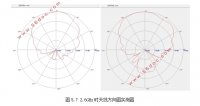
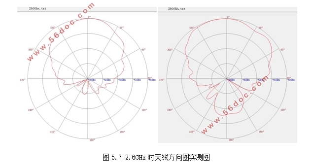
5.2.2方向图...........................................................................................................................29
5.2.3 增益..............................................................................................................................30
6.总结 31
参考文献 32
致谢 33
|