基于STM32的光栅尺位移测量系统设计
来源:56doc.com 资料编号:5D26626 资料等级:★★★★★ %E8%B5%84%E6%96%99%E7%BC%96%E5%8F%B7%EF%BC%9A5D26626
资料以网页介绍的为准,下载后不会有水印.资料仅供学习参考之用. 密 保 惠 帮助
资料介绍
基于STM32的光栅尺位移测量系统设计(论文12700字)
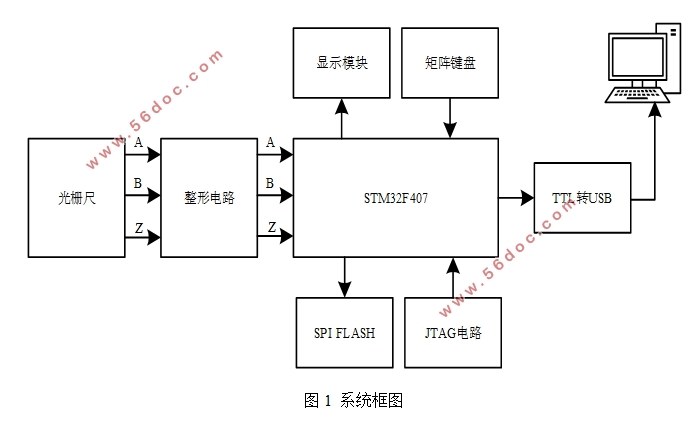
摘要:在工业测试计量领域,通常要对位移量进行精密测量。本文介绍一种基于光栅尺的位移测量系统,以STM32微控制器作为主控芯片。光栅尺提供相位差为90°的两相正弦信号,经过整形电路后连接至STM32的定时器通道。借助STM32定时计数器的正交编码模式,对4倍频的两路方波进行增减计数,最终测得位移量,通过TTL转USB模块传输至PC机,利用C#语言编写Windows Form上位机程序观测测量结果。
关键词:光栅尺;STM32;正交编码;Windows Form
Displacement Measuring System of Grating Ruler Based on STM32
Abstract: In the field of industrial measurement, the precise measurement of displacement is often required. The paper introduces an displacement measuring system of grating ruler, which is controlled by the Micro-Controller of STM32. The grating ruler offers two channels of 90°-phase-difference sine wave, which connect to STM32’s timer channels after a wave-shaping circuit. Taking advantage of STM23 timer’s orthogonal coding pattern, the system increases of decreases the counter according to the 4-multiplying-frequency square wave and finally gets the displacement value. Using the TTL-to-USB module, the system transfers the data to PC and the results can be shown on the Windows Form programmed by C# language.
Keywords: grating ruler; STM32; orthogonal coding; Windows Form
目 录
1绪论 5
1.1课题的研究背景及意义 5
1.2 论文的主要工作和章节安排 5
2 系统整体设计概述 6
2.1 系统设计思路 6
2.2 光栅尺的选型 7
2.3 定时器的正交编码模式 8
3 系统硬件及PCB设计 9
3.1 供电模块 9
3.2 TTL转USB模块 10
3.3 主控模块 11
3.4 程序烧录电路 13
3.5 存储器电路 14
3.6 蜂鸣器电路 15
3.7 整形电路 15
3.8 光栅尺接口电路 16
3.9 矩阵键盘电路 17
3.10 TFT液晶显示屏 18
4 系统软件设计 18
4.1 基于STM32单片机的软件编程 18
4.1.1 开发环境 18
4.1.2 主程序流程 19
4.2 基于C#的上位机软件编程 20
4.2.1 软件开发环境 20
4.2.2 软件开发流程 21
5 系统验证与效果分析 22
6 结束语 24
参考文献 25
致 谢 26
|