充电宝控制电路设计
来源:56doc.com 资料编号:5D26634 资料等级:★★★★★ %E8%B5%84%E6%96%99%E7%BC%96%E5%8F%B7%EF%BC%9A5D26634
资料以网页介绍的为准,下载后不会有水印.资料仅供学习参考之用. 密 保 惠 帮助
资料介绍
充电宝控制电路设计(论文10300字)
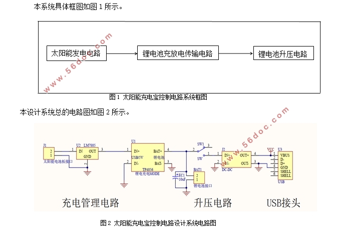
摘要:在当今年代,随着人们科技水平的发展,在众多领域对能源都有着迫切的需要。然而,现实世界中能源的储备往往不充分。导致我们不得不利用新能源来维持自身发展的需要,譬如太阳能。由于太阳能丰富且易于获取,我们应该更好地使用它。本系统设计的目的是制作出成本低廉且具有较高实用性的太阳能充电宝控制电路,它主要由五个部分组成,用于光电转换的太阳能板,用于稳压的降压芯片,用于给锂电池充电的充电模块,存储电源的锂电池,用于为输出升压的升压模块以及USB输出接口。日光可以转化为电能存储在锂电池中,并能够可以经过USB接口输出。本系统通过精简的电路设计,实现了光电转换,为人们室外使用充电宝提供了便捷。
关键词:稳压芯片;充电模块;升压模块。
Design of Battery Charging Control Circuit
Abstract:In today's era, with the development of people's scientific and technological level, there is an urgent need for energy in many fields. However, in the real world, energy reserves are often inadequate. As a result, we have to use new energy to maintain our own development needs, such as solar energy. Solar energy, as an abundant and easy-to-obtain energy, should be well utilized. The purpose of this paper is to make a low-cost and practical control circuit of solar battery charging. It mainly consists of five parts: solar panels for photoelectric conversion, voltage-stabilizing buck chips, charging modules for lithium batteries, lithium batteries for storage power supply, boost modules for output and USB output interface. Sunlight can be converted into electric energy and stored in lithium batteries. It can be output through USB interface. The system realizes photoelectric conversion through simplified circuit design, and provides convenience for people to use portable battery outdoors.
Key words: Voltage regulator chip; Charging module; Boost module.
目 录
1.绪论 1
1.1课题背景及其意义 1
1.2国内外的研究状况 1
1.3本文的设计思路内容和结构安排 2
2. 硬件电路的设计 3
2.1系统的设计组件以及各个组件的具体功能 3
2.1.1系统的设计结构 3
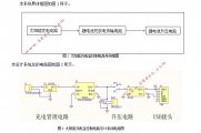
2.1.2系统总体结构 3
2.2模块电路的设计 3
2.2.1太阳能发电电路设计 3
2.2.2 L7805CV电源芯片......................................................................................................................5
2.2.3TP4056锂电池充电模块电路设计 6
2.2.4XL6009升压模块电路设计 7
2.2.5锂电池充电原理.........................................................................................................................9
2.3本章小结...............................................................................................................................................10
3.系统焊接与调试..................................................................................................................................11
3.1 电路焊接 11
3.2 系统调试 11
3.2.1硬件测试 11
3.2.2 实物测试 12
3.3 本章小结 15
4. 总结与展望..........................................................................................................................................16
参考文献 17
致谢 18
|