ЛљгкЕЅЦЌЛњНЛЭЈЕЦЕФЩшМЦ(КЌЕчТЗдРэЭМ,PCBЭМ,ГЬађ)(ТлЮФ18000зж)
еЊ вЊ
ИљОнSTC10F04ЕЅЦЌЛњЕФЬиЕуМАНЛЭЈЕЦдкЪЕМЪПижЦжаЕФЬиЕуЃЌБОЮФЬсГівЛжжгУЕЅЦЌЛњздЖЏПижЦНЛЭЈЕЦМАЪБМфЯдЪОЕФЗНЗЈЁЃЭЌЪБИјГіСЫШэгВМўЩшМЦЗНЗЈЃЌЩшМЦЙ§ГЬАќРЈгВМўЕчТЗЩшМЦКЭГЬађЩшМЦСНДѓВНжшЃЌЖддкЕЅЦЌЛњгІгУжаПЩФмгіЕНЕФживЊЩшМЦЮЪЬтЖМгаЩцзуЁЃБОЮФЖдЪЎзжТЗПкзДЬЌдЄЩшЮЊШ§жжЃЌвЛжжЪЧе§ГЃзДЬЌЃЌвЛжжЪЧНєМБзДЬЌЃЌСэвЛжжЪЧЗНГЬЪНзДЬЌЁЃдіЩшТЗЖЮгіУІЕїећЪБЗНГЬЪНПижЦзДЬЌКЭНєМБЧщПіДІРэФЃПщЃЌЭЈЙ§ЪжЖЏПижЦПЊЙиАДХЅA0КЭA1ЗНБуЯЕЭГдке§ГЃзДЬЌКЭНєМБзДЬЌЁЂЗНГЬЪНПижЦМфРДЛиЧаЛЛЃЌНјвЛВНЭъЩЦСЫНЛЭЈЕЦПижЦЯЕЭГЁЃВЂЗжБ№гУКьЁЂЛЦЁЂТЬЕЦЕФВЛЭЌзщКЯРДжИЛгСНИіЗНЯђЭЈГЕгыНћааЃЌгУLEDЪ§ТыЙмзїЮЊЕЙМЦЪБжИЪОЃЌЪЕЪБЕФПижЦЕБЧАНЛЭЈЕЦЪБМфЪЙLEDЯдЪОЦїНјааЕЙМЦЪБЙЄзїВЂгызДЬЌЕЦБЃГжЭЌВНЃЌдкБЃГжНЛЭЈАВШЋЕФЭЌЪБзюДѓЯоЖШЕФЬсИпНЛЭЈФмЫГГЉНЛЬцдЫааЁЃБОЮФНщЩмСЫПижЦЛљБОдРэвдМАПижЦЕФБэЯжЃЌЭЌЪБЃЌТлЪіСЫЯЕЭГжаНЛЭЈЯжзДЁЂНЛЭЈЙмРэЁЂНЛЭЈЙцдђМАБГОАаХЯЂЁЃ
ЙиМќДЪЃКздЖЏПижЦЃЌЪБМфЯдЪОЦїЃЌЭтВПжаЖЯЃЌбгЪБЃЌЗНГЬЪНПижЦ
Abstract
According to the characteristics of single-chip STC10F04 and traffic lights in the actual control of the characteristics of this paper, a single-chip automatic control with traffic lights and the method of time display. At the same time, given the hardware and software design methodology, design process, including the hardware circuit design and program design two major steps in the single-chip applications that may be encountered in the design of the important issues are involved. In this paper, the default state of the crossroads for three, one is the normal state is a state of emergency, and the other is a state formula. Additional sections of busy status adjustment formula and an emergency control module Through the manual control switch button convenience A0 and A1 system in the normal state and a state of emergency, the equation between the control switch back and forth, and further improve the traffic light control system. And were red, yellow and green light to direct different combinations of traffic in both directions and cut-line, with LED digital tube as a countdown to the instructions, real-time control of the current time for traffic lights to LED countdown display work and to keep pace with the state of light in the to maintain safety while minimizing the increase in traffic to alternate running smoothly. This paper introduces the basic principles of control, as well as the performance of control at the same time, traffic on the system status, traffic management, traffic regulations and background information.
Key words: automatic control; time display; external interrupt; delay; control equation
НЛЭЈЕЦЕФЙЄзїдРэ
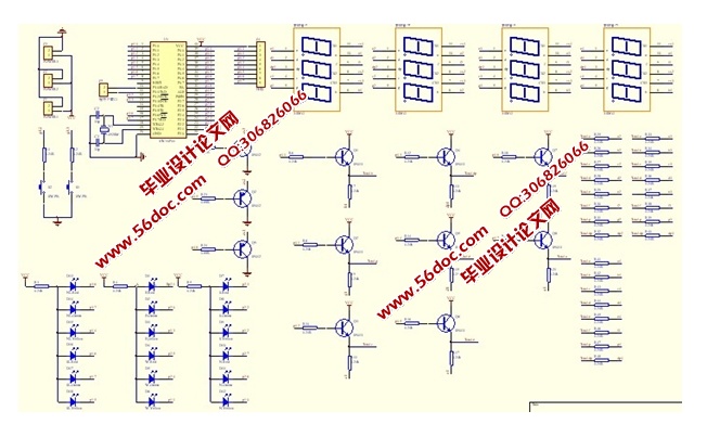
ВЩгУЕЅЦЌЛњЕФI/OПкP1ЁЂP2КЭP3.6ЁЂP3.7жБНгКЭНЛЭЈЕЦСЌНгЃЌP0ЁЂP4ПкЭЈЙ§ЯоСїЕчзшКЭШ§МЋЙмНгLEDЪ§ТыЙмЁЃПижЦГЬађЗХдкSTC10F04ЕЅЦЌЛњЕФROMжаЃЌдкЪЎзжТЗПкЕФЫФзщКьЁЂЛЦЁЂТЬНЛЭЈЕЦжаЃЌгЩЕЅЦЌЛњP1.0-P1.7,P2.0-P2.7КЭP3.6ЁЂP3.7ПижЦЃЌгЩгкНЛЭЈЕЦЮЊЗЂЙтЖўМЋЙмЧвбєМЋЭЈЙ§ЯоСїЕчзшКЭЕчдДе§МЋСЌНгЃЌвђДЫI/OПкЪфГіЕЭЕчЦНЪБЃЌгыжЎЯрСЌЕФЯргІжИЪОЕЦЛсССЃЌВЂЭЈЙ§LEDЪ§ТыЙмЯдЪОЪБМфЕЙМЦЪБЁЃI/OЪфГіИпЕчЦНЪБЃЌЯргІжИЪОЕЦЛсУ№ЁЃНєМБГЕЧыЧѓЭЈЙ§ЕФаХКХгЩШЫЙЄПижЦЃЌвджаЖЯЗНЪНЪфШыЕЅЦЌЛњЃЌЮоНєМБГЕЭЈЙ§ЪБЃЌжаЖЯв§НХINT0(P3.2)ЭЈЙ§ЕчзшКЭЕчдДе§МЋСЌНгЮЊИпЕчЦНЃЌВЛВњЩњжаЖЯЃЌЕЅЦЌЛњжДаажїГЬађЃЌгаНєМБГЕЭЈЙ§ЪБЃЌжаЖЯв§НХINT0(P3.2)ВЩгУШЫЙЄЗНЗЈНгЕиЮЊЕЭЕчЦНЃЌВњЩњжаЖЯЧыЧѓЃЌЕЅЦЌЛњжДаажаЖЯЗўЮёГЬађЃЌШУНєМБГЕЭЈЙ§ЃЌНєМБГЕЭЈЙ§КѓЃЌжаЖЯв§НХINT0(P3.2)БфЮЊИпЕчЦНЃЌЗЕЛижїГЬађЁЃЗНГЬЪНПижЦЭЈЙ§ЕФаХКХгЩШЫЙЄПижЦЃЌвджаЖЯЗНЪНЪфШыЕЅЦЌЛњЃЌВЛашЕїећжмЦкЪБЃЌжаЖЯв§НХINT1ЃЈP3.3ЃЉЭЈЙ§ЕчзшКЭЕчдДе§МЋСЌНгЮЊИпЕчЦНЃЌВЛВњЩњжаЖЯЧыЧѓЃЌЕЅЦЌЛњжДаажїГЬађЃЌЕБГЕСОЖрашвЊдіМгжїИЩЕРЭЈГЕЪБМфЪБЃЌжаЖЯв§НХINT1ЃЈP3.3ЃЉВЩгУШЫЙЄЗНЗЈНгЕиЮЊЕЭЕчЦНЃЌВњЩњжаЖЯЧыЧѓЃЌЕЅЦЌЛњжДаажаЖЯЗўЮёГЬађЃЌЯЕЭГвдЗНГЬЪНПижЦЃЌАДвЛДЮПЊЙиАДХЅA1жДааЗНГЬЪНAЃЌАДСНДЮПЊЙиАДХЅA1ЪБжДааЗНГЬЪНBЃЌАДШ§ДЮПЊЙиАДХЅA1ЪБжДааЗНГЬЪНCЁЃЕБАДЫФДЮЪБЃЌжаЖЯв§НХЮЊИпЕчЦНЃЌЗЕЛижїГЬађЁЃ
ФП ТМ
еЊ вЊ 1
Abstract 2
ФП ТМ 3
1 аїТл 4
1.1 НЛЭЈЕЦбаОПЕФБГОАКЭвтвх 4
1.2 НЛЭЈЕЦЙњФкЭтЗЂеЙИХПі 4
2 ЯЕЭГЙЄзїдРэМАЩшМЦЗНАИ 7
2.1 НЛЭЈЕЦЕФЙЄзїдРэ 7
2.2 НЛЭЈЕЦзмЬхЩшМЦЗНАИ 7
3 гВМўЯЕЭГЩшМЦ 11
3.1 гВМўЯЕЭГзщГЩ 11
3.1.1 ЕЅЦЌЛњзюаЁЯЕЭГ 11
3.1.2 аХКХЯдЪОЧ§ЖЏЕчТЗ 15
3.1.3 МќХЬЪфШыЕчТЗ 16
4 НЛЭЈЕЦЯЕЭГЯъЯИЩшМЦ 18
4.1 ШэМўзмЬхЩшМЦЫМЯы 18
4.2 НЛЭЈПижЦЫуЗЈЪЕЯж 20
4.3 ЯЕЭГГѕЪМЛЏФЃПщ 21
4.4аХЯЂЯдЪОФЃПщ 22
4.4.1 аХКХЕЦФЃПщ 22
4.4.2 LEDЕЙМЦЪБЯдЪОзгГЬађ 26
4.5МќХЬЩЈУшФЃПщ 29
5 ЕїЪНзмНс 37
6 жТ аЛ 38
ВЮПМЮФЯз 39
ИН ТМ 40
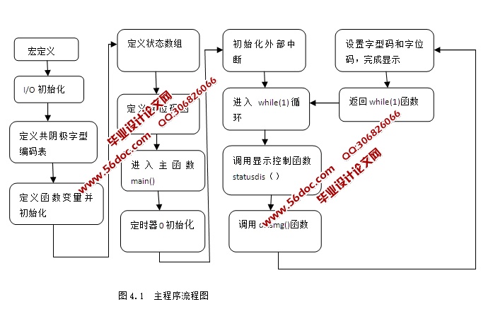
ИНТМвЛ ГЬађЧхЕЅ 40
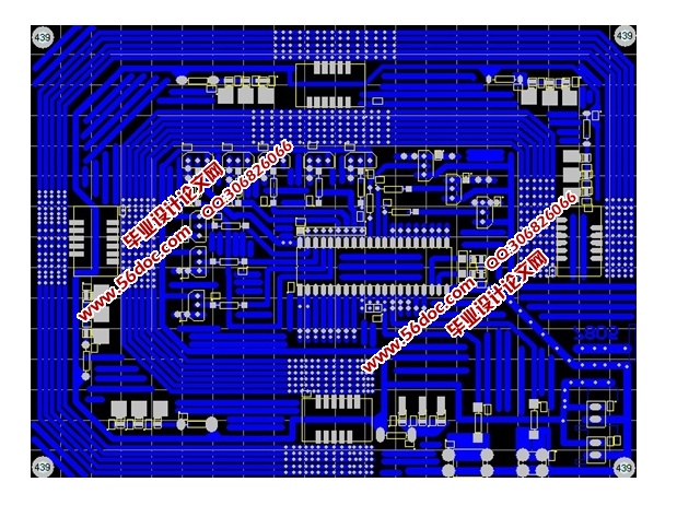
ИНТМЖў НЛЭЈЕЦPCBЭМ 48
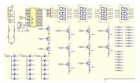
ИНТМШ§ НЛЭЈЕЦЕчТЗдРэЭМ 49
|