基于单片机任意函数信号发生器的设计(附程序代码)(任务书,开题报告,外文翻译,论文12000字,程序代码)
摘 要
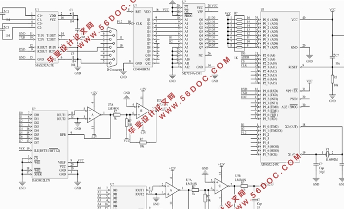
信号发生器作为常用的信号源,广泛地应用于自动控制系统、电子电路和教学实验等领域。而目前使用的最广泛的便是函数信号发生器,但特殊波形发生器的价格昂贵。然而本设计采用AT89C51单片机构成发生器,可产生方波、正弦波、三角波等多种特殊波形,并且波形的频率与幅值可用上位机进行控制和显示。然后在单片机的输出端口接两个DAC0832,其中一个是用来保持已调波形的原波形,另一个是通过P2口来调节波形的幅值,最后将输出波形显示在在示波器上。由于硬件电路较少、不限简洁,所以本设计既有功能齐全的特点,成本也相对较低。
关键词:上位机;单片机;串口控制;频率控制;幅值控制;D/A转换
Abstract
The signal generator used as a signal source is widely used in the field of automatic control system, electronic circuit and experimental teaching. At present, the most widely used is the function signal generator, but the price of special waveform generator is very expensive. However this design using AT89C51 micro-controller generator,can generate square wave, sine wave, triangle wave,which contains a variety of special waveform and arbitrary waveform, and waveform of the frequency and amplitude can be controlled and displayed by host machine with the output port of the single chip microcomputer connected two DAC0832. One of which is used to keep the original modulated wave, another one is used to adjust the amplitude of the waveform through the P2 mouth, finally output waveform is then displayed on the oscilloscope. Because the hardware circuit is less, wiring is simple, so this design has the characteristic of complete function and low cost.
Key words:host computer; single chip microcomputer; frequency control; amplitude control; D/A transform
目录
第1章 绪论 1
1.1 课题的来源与技术背景 1
1.2 研究信号发生器的目的及意义 1
1.3 主要研究内容 2
第2章 电路方案的确定 3
2.1 方案的提出和选择 3
2.1.1方案的提出 3
2.1.2方案的选择 3
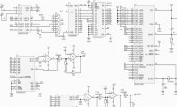
2.2 电路框图及工作原理 4
第3章 单元电路设计 6
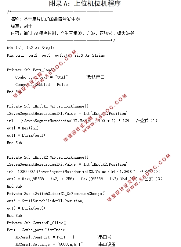
3.1 上位机模块 6
3.1.1 显示部分 6
3.1.2 控制模块 7
3.2 单片机模块 7
3.3 串口控制模块 9
3.3.1 VB串口控制 9
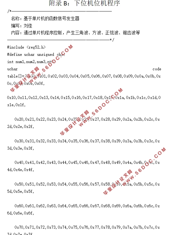
3.3.2 下位机串口控制 10
3.4 频率控制模块 11
3.4.1 单片机的定时器中断控制 11
3.4.2 CD4040计数器的控制 13
3.4.3 EPROM2764的控制 14
3.5 幅值控制模块 15
3.6 D/A转换模块 15
第四章 电路软件设计 20
4.1系统总框图 20
4.2 上位机显示和控制图 21
第五章 设计实现与总结 22
5.1输出波形的种类与频率的测试 22
5.2仿真结果的的分析 26
总 结 28
致谢 30
|