重载无人驾驶电动集装箱运输车车体车架系统设计(英文版)(含CAD图,UG三维图)(任务书,文献摘要,外文翻译,论文说明书英文版9000字,CAD图5张,UG三维图)
Design of Body And Frame System of Heavy-duty Electric Automatic Guided Containers Transporting Vehicle
Abstract
In order to improve transportation efficiency, reduce costs, streamline management, and improve port transportation environment, etc., one of the development trends of container terminals is to promote the development of container terminals in the direction of automation and intelligence. The heavy-load unmanned electric container transport vehicles (AGV) is a key link in the automation and intelligentization of container terminals. The design of frame and body of the heavy-load unmanned electric container transport vehicles is the key. Strength and stiffness are the crucial factors on designing its frame. The crucial factors on designing its body are providing installation position of some assembles like the battery system and fixing containers when carrying. Due to the heavy load of this AGV and its own large mass, and its function of bearing its own mass and various of load as well as providing position for installing other assembles, the design of frame will be mainly illustrated, including the design procedures of the main frame and the auxiliary frame. After obtaining the parameters of frame by numerical calculation, the three-dimensional model of frames are built with UG 10.0 and the finite element analysis is conducted on them, which will provide more direct and detailed judgement for the frame.
The research result indicate that: the design frame can meet the requirement of strength and stiffness, and providing installation position for other assembles. Besides, the vehicle body realize its function.
The feature of this paper: the AGV involved in this article is a super-heavy unmanned electric vehicle. The frame is said to bear heavy loads. In order to ensure that the frame meets the requirements, both numerical calculations and finite element analysis will be applied.
Key Words:AGV; main frame; auxiliary frame; vehicle body; stiffness; strength; finite element analysis


Catalogue
Abstract 1
Ⅰ Introduction 1
1.1 The development of automation in port transportation industry 1
1.2 The development status of port AGV 2
1.3 Basic design content of franme and body system 4
Ⅱ Design of main frame 6
2.1 Common frame structure types 6
2.1.1 Side-beam frame 6
2.1.2 Circumjacent frame 7
2.1.3 X-shape frame 8
2.1.4 Backbone-type frame 8
2.1.5 Integrated frame 9
2.1.6 Summary 9
2.2 Determination of the section shape of the longitudinal beam 9
2.3 Selection of the material of the longitudinal beam 10
2.4 Selection of the material of the longitudinal beam 10
2.5 Analysis of loads on longitudinal beam 12
2.5.1 Types of loads on longitudinal beam 12
2.5.2 Stress situation analysis 13
2.5.3 Calculation and check of stiffness 17
2.6 Beam arrangement and type selection 19
2.6.1 Arrangement of cross beams 20
2.6.2 Selection of the type of cross beams 24
2.7 Beam arrangement and type selection 24
2.7.1 Selection of connection methods for longitudinal beams and cross beams 24
2.7.2 Selection of welding method 25
Ⅲ Design of sub-frame 27
3.1 Determination of cross-section size and shape of sub-frame 27
3.2 Calculation and examination of the longitudinal beam of sub-frame 27
3.3 Determination of shape of the end of sub-frame 29
3.4 The arrangement of cross beams of sub-frame 30
3.5 The connection methods of longitudinal beams and cross beam 31
3.6 The connection methods of main frame and sub-frame 31
Ⅳ Design for the body system 34
4.1Limiting-container overhanging beam 34
4.2Limiting-container box 35
4.3 battery system and central control system overhanging beam 37
4.4 supporting-body beams 38
4.5 Mounting-motor brackets 39
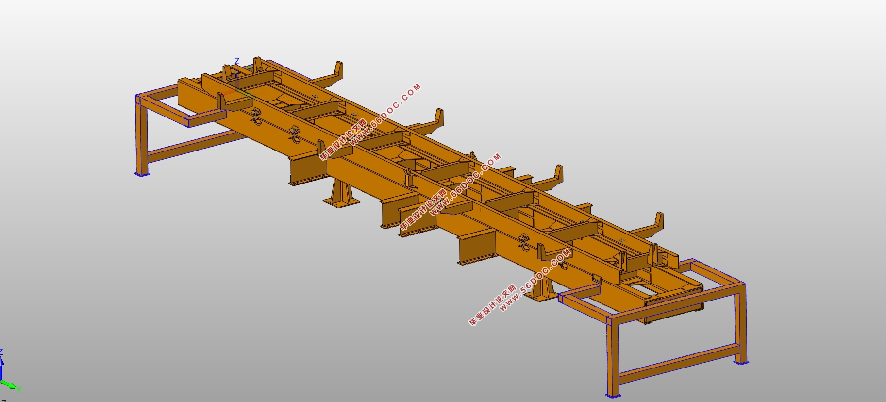
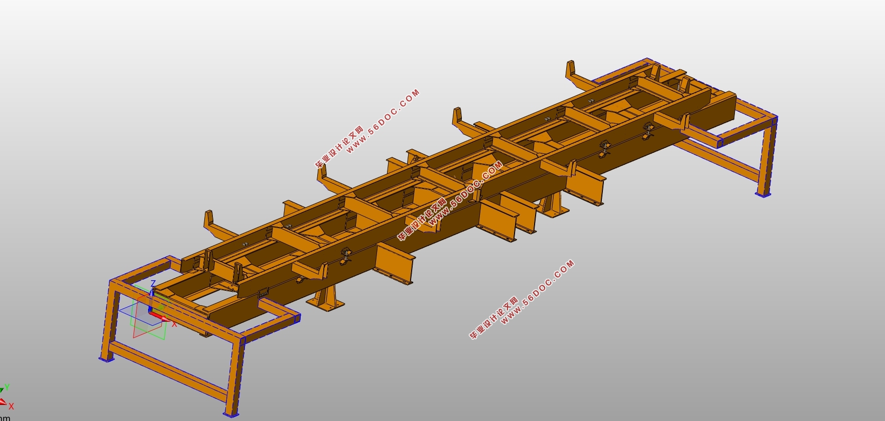
4.6 Body and frame system assembly 39
Ⅴ Finite Element Analysis of Frames 41
5.1Application of Finite Element Analysis in Frame Design 41
5.2 Finite element analysis scheme 42
5.2.1 Simplification of the model 42
5.2.2 Constrains and loads that load on frames 42
5.3 Simulation results of only the main frame bearing stress 43
5.4 Simulation results of the sub-frame assembled on the main frame 45
5.5 Analysis by comparing two finite element analysis results 48
Ⅵ Conclusions 50
Acknowledgements 51
References 52
|
