新能源汽车驱动桥主减速器动力性能设计(含CAD图)(任务书,开题报告,论文说明书12000字,CAD图5张)
摘要
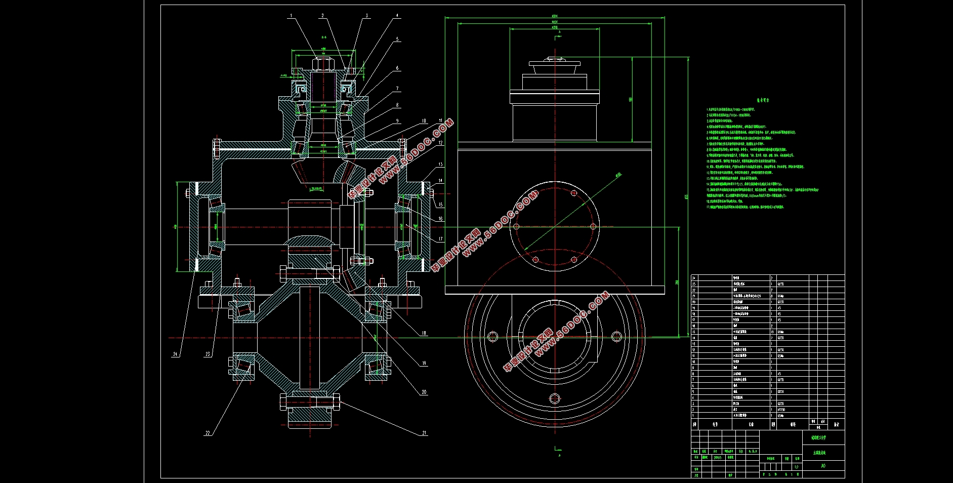
这次设计是要为某新能源汽车设计一个采用双级减速的主减速器,要求设计的主减速器符合设计原理,工作稳定,达到新能源汽车的要求。主减速器是一个可以同时改变转速和转矩的零件。基本作用是可以增大传递到驱动桥内的转矩并根据实际情况更改转矩的方向,传递的扭矩从具有少量齿数的锥齿轮传递到具有大量齿数的锥齿轮。与单级减速相比,设计的最终传动方案是两级齿轮一起用于减速。双级减速获得的传动比更高,而且采用双级减速的汽车离地间隙比单级减速更大,而且它更便于生产制造,工作原理简单且稳定,使用时间长,所以双级减速器更适用与新能源汽车。本次设计的内容包括有:选择适用的齿轮类型和减速形式,对齿轮、轴和轴承进行合理设计,确保整个主减速器能够平稳安全的工作,完成设计指标。
关键词:双级减速;设计计算;三维建模;运动仿真。
Abstract
This design is to design a two-stage deceleration main reducer for a new energy vehicle, which requires that the main reducer conforms to the design principle, works stably and meets the requirements of the new energy vehicle. The main reducer is a part that can change the speed and torque at the same time. The basic function is to increase the torque transferred to the drive bridge and change the direction of the torque according to the actual situation, and the transmitted torque can be transferred from the bevel gear with a small number of teeth to the bevel gear with a large number of teeth. Compared with single-stage deceleration, the final transmission scheme is used for deceleration with two-stage gears. The transmission ratio of the two-stage deceleration is higher, and the ground clearance of the vehicle with two-stage deceleration is larger than that of the single-stage deceleration, and it is more convenient for production and manufacture, the working principle is simple and stable, andthe service time is long, so the two-stage reducer is more suitable for new energy vehicles. The contents of this design include: select the suitable gear type and deceleration form, carry on the reasonable design to the gear, shaft and bearing, ensure that the whole main reducer can work smoothly and safely, and complete the design index.
Key words:two-stage deceleration; design calculation; 3D-Modellierung.
初始数据
基本设计参数:
电机部分:额定功率Pw =30 Kw,额定转速N =4000r/min,额定电压U =120V;
整车部分:汽车整备质量 m=1340 kg,前轴荷 m1=615 kg,后轴荷 m2=725 kg,质心高 hg=670 mm,轴距 L=2850 mm,车轮滚动半径 R=300 mm。

目录
第一章绪论 1
1.1、发展前景及意义 1
1.2、初始数据 1
1.3、设计任务 1
1.4、主减速器设计的要求 2
1.5、研究目标 2
第二章主减速器结构分析 3
2.1根据齿轮类型分析 3
2.2根据减速形式分析 4
2.3主动锥齿轮和从动锥齿轮的支承形式 7
第三章主减速器设计计算 9
3.1 主减速器中齿轮的设计计算 9
3.1.1主减速器锥齿轮的主要参数选择 9
3.1.2主减速器圆柱齿轮主要参数选择 11
3.2主减速器计算载荷的确定 12
3.2.1主减速器锥齿轮的强度计算 12
3.2.2 锥齿轮的材料 13
3.3 主减速器的润滑 13
第四章轴承与轴的选择和校核 14
4.1轴和轴承的设计计算 14
4.1.1 主动齿轮轴轴承的校核 14
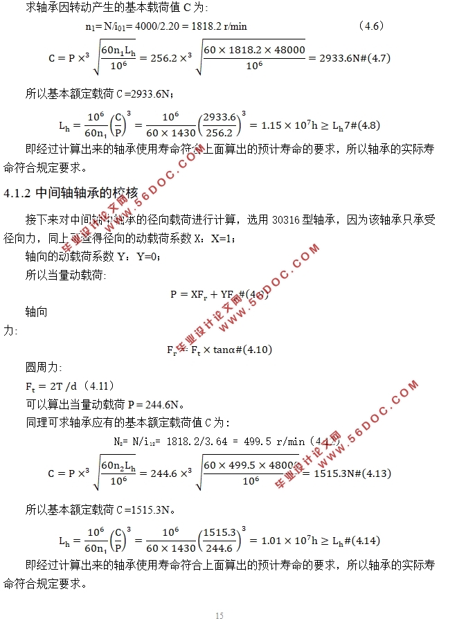
4.1.2中间轴轴承的校核 15
4.1.3轴承的预紧 16
4.2 轴的结构设计 16
4.3轴的校核 17
4.3.1 主动圆柱齿轮轴的校核 17
4.3.2中间轴的校核 19
第五章主减速器的三维建模及仿真分析 22
5.1三维模型 22
5.2运动仿真分析 24
致谢 26
参考文献 27
|