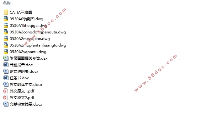
大众新捷达离合器设计(含CAD零件图装配图,CATIA三维图)(任务书,开题报告,文献摘要,外文翻译,论文说明书11000字,CAD图纸6张,CATIA三维图)
摘要
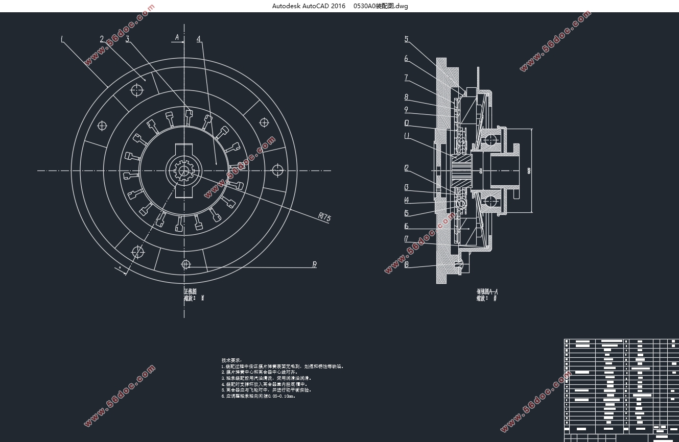
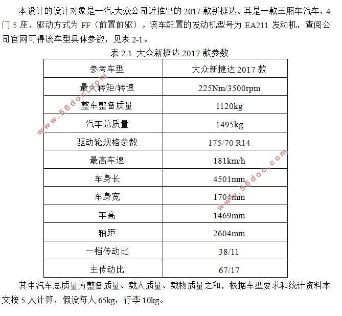
捷达系列轿车作为紧凑型车类的代表,在中国市场表现不俗。本文在传统的离合器结构基础上,针对一汽大众公司推出的2017款捷达轿车进行离合器设计。本文的主要任务是完成离合器总成设计并进行关键零部件仿真分析。
本文的重点分为三部分:离合器的工作原理及结构分类;总成及零部件的设计;关键零部件ANSYS分析。首先,根据离合器的研究背景及相关发展近况,就设计2017款大众新捷达离合器的主要研究内容、目的和意义进行了阐述。再者,分章节进行阐述离合器零件及总成的选择及设计计算。最后利用ANSYS有限元分析进行了从动盘毂的静应力和模态分析,保证设计的离合器满足要求能正常工作。
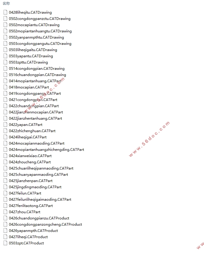
本文利用了CAD、CATIA和ANSYS等计算机软件,极大地缩小了设计工作量,提高了设计效率,为厂家进行离合器设计提供了理论指导和实践支持。
关键字:离合器;设计;膜片弹簧
Abstract
The Jetta sedan has a high sales in China market. On the basis of the traditional clutch structure, this paper designs the clutch for the 2017 Jetta cars. The main task of this paper is to complete the design of clutch assembly, and to do the simulation analysis of key components.
The paper is divided into three parts: the working principle and classification of the clutch, the design of the assembly and parts, and the analysis of the key components with ANSYS. First of all, according to the background and related development, the content, purpose and significance of the research are described. In addition, the selection and design calculation of clutch parts and assembly are discussed in chapters. Finally, the static stress and modal analysis of the driven disk hub are carried out by finite element analysis, so that the designed clutch can meet the requirements and work properly.
This paper makes use of computer software such as CAD, CATIA and ANSYS, which greatly reduces the design workload and improves the design efficiency. It provides theoretical guidance and practical support for the clutch design of the manufacturers.
KeyWords:clutch;design;diaphragm spring
目录
第1章绪论 1
1.1 课题研究背景 1
1.2 设计目的及意义 1
1.3 国内外研究现状 2
1.4 研究内容及预期目标 2
第2章确定离合器方案 4
2.1 分析车型 4
2.2离合器结构方案 4
2.2.1 从动盘数 5
2.2.2 压紧弹簧的结构形式 5
2.2.3 膜片弹簧的支承形式 6
第3章离合器基本参数 7
3.1 后备系数β 7
3.2摩擦系数f 7
3.3摩擦片设计参数 7
3.4 单位压力P0 8
3.5校核离合器基本参数 8
3.5.1最大圆周速度 8
3.5.2 单位摩擦面积传递力矩Tc0 8
3.5.3滑磨功ω 9
第4章离合器结构零件设计 10
4.1 从动盘总成设计 10
4.1.1 从动盘总成结构型式 10
4.1.2 从动片结构型式 10
4.1.3 从动盘毂 11
4.2 离合器盖设计 12
4.3 压盘设计 13
4.3.1压盘几何尺寸 13
4.3.2压盘温升校核 14
第5章膜片弹簧设计 15
5.1膜片弹簧几何参数 15
5.1.1 H/h比值和h的选择 15
5.1.2自由状态下碟簧大端半径R、小端半径r 15
5.1.3膜片弹簧起始圆锥底角α 15
5.1.4 其他设计参数 15
5.2基本参数校核 16
5.3 膜片弹簧工作点位置的选择 16
5.4 强度校核 18
第6章扭转减振器设计 20
6.1基本设计参数选择 20
6.1.1极限转矩Tj 20
6.1.2 扭转角刚度kφ 20
6.1.3阻尼摩擦转矩Tμ 20
6.1.4 预紧转矩Tn 20
6.1.5 减振弹簧位置半径R0 20
6.1.6 减振弹簧总压力FΣ 21
6.2减振弹簧设计 21
6.2.1 减振弹簧参数 21
6.2.2 减振弹簧刚度K 21
6.2.3 减振弹簧的有效圈数i 21
6.2.4 减振弹簧长度及变形量 22
6.3 其他设计 22
6.3.1限位销与从动盘缺口侧边的间隙λ 22
6.3.2从动盘毂安装窗口及缺口设计 22
第7章操纵机构 24
7.1 操纵机构设计 24
7.2 操纵机构校核 24
7.2.1自由行程 24
7.2.2工作行程 25
7.2.3踏板总行程 25
7.2.4 踏板力校核 25
第8章从动盘毂分析 26
8.1 建立从动盘毂模型 26
8.2 静应力分析 27
8.2.1约束及加载 27
8.2.2输出结果与分析 27
8.3 模态分析 27
结论 29
参考文献 30
致谢 31
|