曲轴箱箱体左侧面3×M6螺纹底孔组合钻床及夹具设计(含CAD图)(任务书,开题报告,外文翻译,论文说明书7600字,CAD图纸7张,生产率计算卡)
摘 要
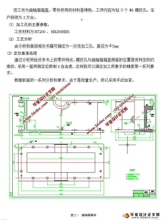
本文对曲轴箱箱体孔的加工工艺进行了详细的分析,对左侧面3×M6的孔提出了异种思路,那就是通过一次装夹还有单工位加工。本文对各部分的设计进行了详细的计算和论证。
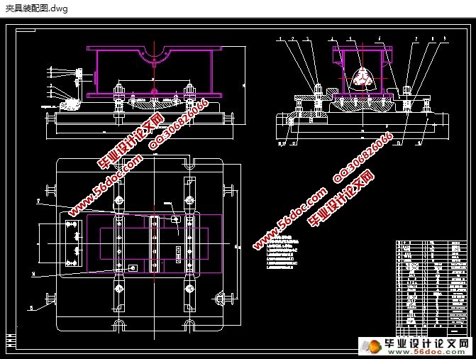
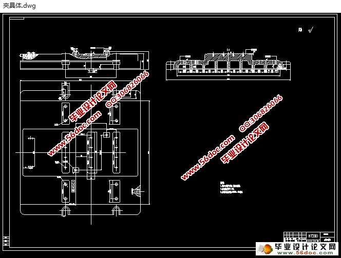
在机床设计部分涉及选择合适的切削用量、进给参数及机床的配置,并完成此次设计最重要的一个环节 “三图一卡”的绘制。夹具设计部分主要涉及定位基准的选择以及夹紧方案的确定,计算并检验夹紧力,最后绘制夹具装配图。
关键词:组合机床;钻孔;夹具设计;手动
Crankcase side left box 3 x M6 thread bottom hole combination drilling machine and fixture design
Abstract
In this paper, the crankcase box body processing technology has carried on the detailed analysis, on the left proposes the heterogeneous 3 x M6 , that is through a and simplex processing. In this paper, the design of each part has on the detailed calculation and demonstration.
The overell design specifies choice of such factors as the positining datum of processing, grip program, preper cutting parameters, cutting tools, the coafiguration types of machine tools. Meanwhile the drawing of “Three Charts and One Card” are completed. To design fixture design, the first to identify the workpiece positioning programme, Finally, according to the results, draw fixture assembly and major parts of the map.
Key words: Modular machine tool; Fixture Synchronizing; Location ; Spindle Box
目 录
摘 要 3
Abstract 4
1 绪论 5
1.1 组合机床的国内外研究情况 5
1.2 组合机床的特点 5
1.3 组合机床的方案选择 5
1.4 组合机床夹具概述 5
1.5本课题的意义 6
2 组合机床的总体设计 7
2.1 组合机床方案的制定 7
2.1.1 制定工艺方案 7
2.1.2 确定组合机床的配置形式和结构方案 7
2.2 确定切削用量及选择刀具 8
2.2.1 确定工序间余量 8
2.2.2 选择切削用量 8
2.2.3 确定切削力、切削扭矩、切削功率 9
2.2.4 选择刀具结构 9
2.3 钻孔组合机床总体设计“三图一卡”的编制 10
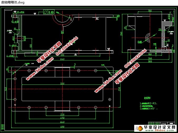
2.3.1 被加工零件工序图 10
2.3.2 加工示意图 11
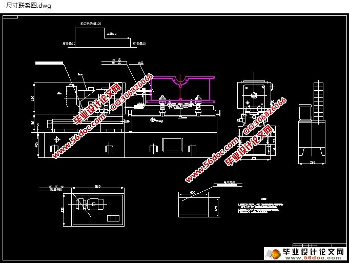
2.3.3 机床联系尺寸图 15
2.3.4 生产率计算卡 18
3 多轴箱的设计 20
3.1 绘制多轴箱设计原始依据图 20
3.2 齿轮模数选择 21
3.3 多轴箱的传动设计 21
3.4 绘制传动系统图 23
4 钻孔夹具设计 26
4.1 研究原始资料 26
4.2 定位、夹紧方案的选择 26
4.3切削力及夹紧力的计算 26
4.4 误差分析与计算 27
4.5 钻模板设计与选用 28
4.6夹具设计及操作的简要说明 28
结论 30
参考文献 31
致 谢 32
|