轴承内外圈加工专用机床纵向机构设计(CAD,UG三维及仿真)(任务书,开题报告,外文翻译,进度计划表,论文说明书18000字,cad图纸9张,UG三维模型及运动仿真)
摘 要
随着轴承工业的迅速发展,对轴承的加工精度、效率、可靠性提出了更高的要求。尺寸精度是轴承加工中的一项关键因素,而车床的进给机构直接影响轴承套圈加工的尺寸精度。因此,随着对轴承质量要求的不断提高,需要更加精密高效的车床进给机构。
本文是根据轴承厂轴承内外圈加工生产线项目的改造要求设计的,针对人工控制机床的进给加工,加工效率低,生产出的零件精度难于控制的问题,设计一套此车床的半自动进给机构,代替传统机床的人工操作,提高生产效率,提高零件的精度。
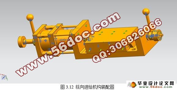
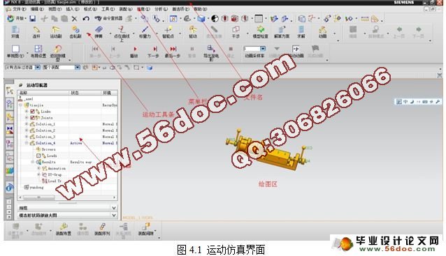
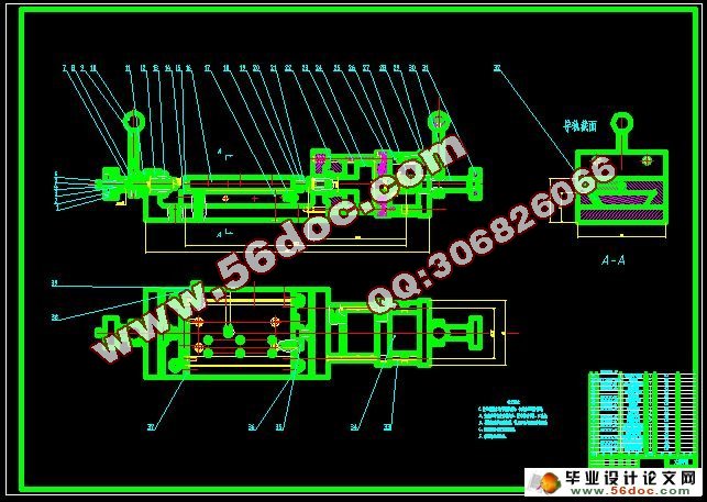
论文根据轴承内外圈加工设备加工时进给的特点,对其纵向进给机构进行合理的设计。设计出利用液压驱动,前、后调节机构调节进给量的纵向进给机构。本文先对液压驱动系统、导向机构、前调节机构、后调节机构进行设计,确定具体尺寸。利用UG软件对纵向进给机构进行三维建模,并进行虚拟装配。然后对装配图在UG运动仿真界面进行运动仿真,分析仿真结果,得出相应结论。最后对纵向进给系统进行优化设计,提高其稳定性、可靠性。使其能满足轴承厂生产线繁重的工作。
关键词:进给机构;UG;虚拟装配;运动仿真
Abstract
With the rapid development of bearing industry, the working accuracy, efficiency and reliability of bearing have been put forward higher requirements.A essential factor of bearing process is the dimensional accuracy, however, the feeding system of machine tools directly affects the dimensional precision of bearing ring process. Therefore, with the constant improvement of bearing's quality requirements, it is necessary for the feeding system of machine tools to become more precise and efficient.
This paper is based on the requirements of bearing inner and outer ring process production line project in bearing factory. As the process efficiency is low by the manual control of the machine feed process and the precision of the parts production is difficult to control. This paper designs a lathe of semi-automatic feed mechanism to instead of manual operation of conventional machines, in order to improve production efficiency and the part accuracy.
This paper has a reasonable design of vertical feed mechanism what is based on the characteristic of feed processing by bearing inner and outer rings process equipment. The aim of this paper is designing a longitudinal feed mechanism through using hydraulic drive, before and after the vertical regulating mechanism adjust the feed. The paper devises a process equipment what is using hydraulic drive and before and after the adjustment mechanism to adjust the feed rate and after that identifies a specific size. This paper uses UG software for proceeding 3D modeling of longitudinal feed mechanism and virtual assembly, after that carries out on the motion simulation by assembly drawings in UG motion simulation interface and analysis of the simulation results, and ultimately obtains the corresponding results. Finally, the paper optimizes the design for the longitudinal of feed system, improving the stability and reliability, which is for meeting heavy work of the production line in bearing factory.
Key words: feed mechanism; UG; virtual assembly; motion simulation
本课题主要内容包括:
1.对实际生产和要求进行分析,制定出可行的机构设计方案;
2.对机构的零件进行设计;
3.对设计出的结构进行三维建模;
4.对三维模型运动仿真,对仿真结果进行分析;
轴承内外圈在加工过程中轴主要以人工控制加工为主,由工人的动控制进给量。发生生产事故或者使加工零件报废一般发生在工人长时间重复单一动作的的时候。为了改善工作环境;降低工人的劳动强度;提高生产效率和零件的精度。轴承内外圈加工专用机床自动纵向进给机构的研制使其能真正代替人工工作。工人只要按动按钮。此机构的工作方式使其能实现一人多机操作;可以使大量工人从中解放出来;提高了加工精度;降低了企业生产成本;使企业更加有竞争力!
目 录
摘 要 III
ABSTRACT IV
目 录 V
1 绪论 1
1.1 课题来源,研究内容和意义 1
1.2 轴承与轴承圈 1
1.2.1 轴承 1
1.2.2 轴承圈 2
1.3 国内外发展概况 2
1.4 本课题主要内容 3
2 纵向自动进给机构设计 4
2.1 现有机构及生产要求的分析 4
2.2 整体设计方案及思路 5
2.3 纵向进给机构各部分的设计与计算 6
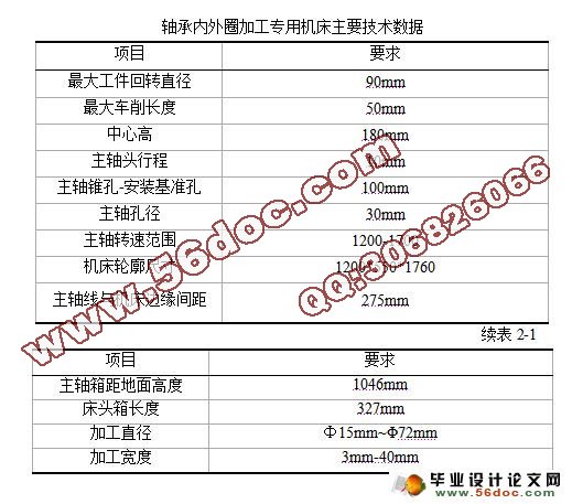
2.3.1 纵向进给机构外形轮廓确定 6
2.3.2 导向机构设计 7
2.3.3 驱动装置的选取 9
2.3.4 前调节机构设计 12
2.3.5 后调节机构设计 12
2.4 本章小结 13
3基于UG的进给机构三维建模与装配 14
3.1 UG软件简介 14
3.1.1 UG软件特点 14
3.1.2 UG软件设计流程 14
3.1.3 UG软件的应用范围 14
3.1.4 UG软件设计的意义 15
3.2 纵向机构的三维建模 15
3.2.1 纵向底板的建模 15
3.2.2 纵向燕尾板建模 16
3.2.3 刹铁的建模 16
3.2.4 纵向台面板的建模 17
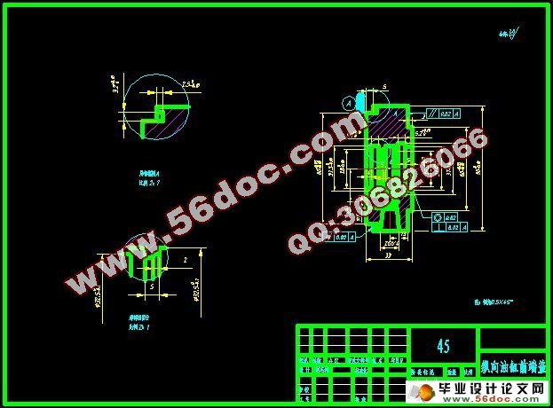
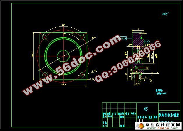
3.2.5 油缸的建模 19
3.2.6 前调节机构的建模 19
3.2.7 后调节机构的建模 20
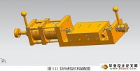
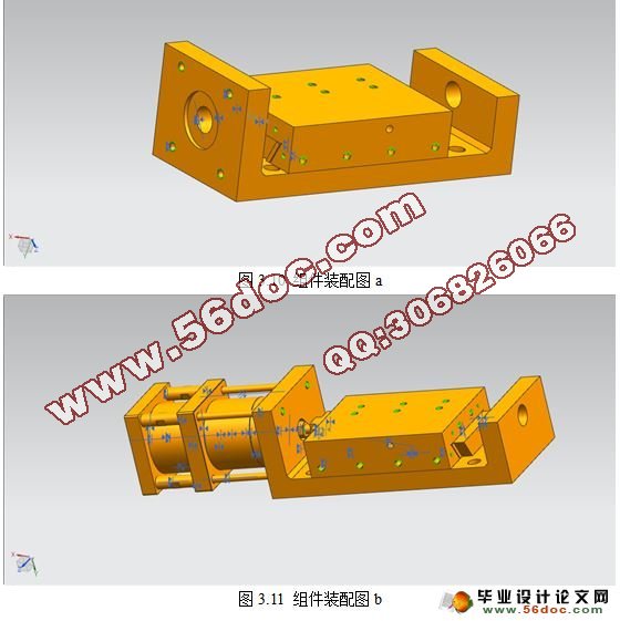
3.3纵向进给机构的装配 20
3.4本章小结 23
4 纵向自动进给机构的运动仿真 24
4.1 UG运动仿真简介 24
4.1.1 UG运动仿真主界面 24
4.2运动仿真的流程 25
4.3创建连杆 26
4.4创建运动副 27
4.5创建驱动及“3D”接触 29
4.6 本章小结 35
5 总结与展望 36
5.1 总结 36
5.2 不足及展望 36
致 谢 37
参考文献 38
|