ЭкЛњЛизЊЛњЙЙЩшМЦгыаЃКЫ(КЌCADЭМ,PROEШ§ЮЌЭМ)
РДдДЃК56doc.com зЪСЯБрКХЃК5D21952 зЪСЯЕШМЖЃКЁяЁяЁяЁяЁя %E8%B5%84%E6%96%99%E7%BC%96%E5%8F%B7%EF%BC%9A5D21952
зЪСЯвдЭјвГНщЩмЕФЮЊзМ,ЯТдиКѓВЛЛсгаЫЎгЁ.зЪСЯНіЙЉбЇЯАВЮПМжЎгУ. Ум БЃ Лн Аяжњ
зЪСЯНщЩм
ЭкЛњЛизЊЛњЙЙЩшМЦгыаЃКЫ(КЌCADЭМ,PROEШ§ЮЌЭМ)(ШЮЮёЪщ,ПЊЬтБЈИц,ЭтЮФЗвы,ТлЮФЫЕУїЪщ9000зж,CADЭМ4еХ,PROEШ§ЮЌЭМ)
еЊвЊ
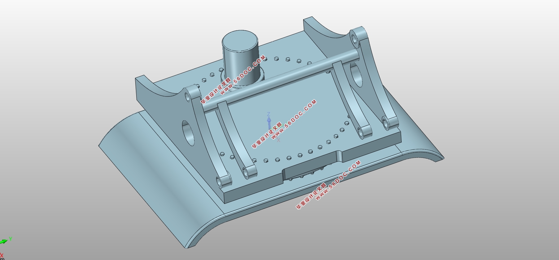
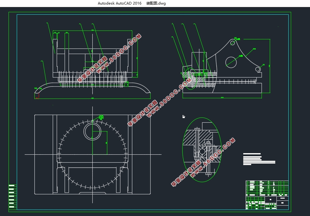
ЫцзХЮвЙњОМУЕФЗЂеЙЃЌЖдгкЛљДЁЩшЪЉНЈЩшЕФашЧѓдНРДдНДѓЁЃЭкОђЛњзїЮЊЛљНЈЙЄГЬжаЕФживЊЛњаЕЃЌдкИїжаЭкОђЁЂВЩПѓаавЕжаЖМЕУЕНСЫКмДѓЕФгІгУЁЃЖјЛизЊЛњЙЙзїЮЊЭкОђЛњЕФКЫаФВПМўЃЌЦфбаЗЂКЭгХЛЏвЛжБвдРДЪЧвЛЯюживЊЕФПЮЬтЁЃБОЮФЯШВћЪіСЫПЮЬтЕФбаОПБГОАЃЌНгзХЖдЛизЊЛњЙЙЕФЗЂеЙЯжзДЁЂЗЂеЙЧїЪЦЁЂЕфаЭЗжРрНјааСЫНщЩмЃЛШЛКѓЭЈЙ§МЦЫуЃЌбЁГіКЯЪЪЕФЛизЊЛњЙЙЕФСуМўВЂЖдЦфНјааЧПЖШаЃКЫЃЛВЂНщЩмСЫвЛЬзЙІФмЧПДѓЕФЙЄГЬФЃФтЕФгаЯодЊШэМў——ABAQUSЃЌАќРЈABAQUSЕФжївЊЙІФмМАгІгУСьгђЕШЃЌзюКѓЭЈЙ§гаЯодЊШэМўABAQUSЖдЛизЊжЇГаНјаагІСІЗжЮіЁЃ
ЙиМќДЪЃКЛизЊЛњЙЙЛизЊжЇГадиКЩЗжЮігаЯодЊЗжЮі
The design and check of excavator slewing mechanism
ABSTRACT
With the development of our economy, the demand for infrastructure construction is increasing.As the important machinery in infrastructure projects, excavators have been widely used in mining industries .The rotary mechanism as a core component of the excavator, its research and optimization has always been an important issue.This paper firstly describes the research background of the project. Then the paper introduces the development status, development trend and typical classification of excavator slewing mechanism. And through the design calculation, the appropriate parts of the slewing mechanism are selected and the strength check is carried out. Then a set of powerful engineering simulation finite element software—ABAQUS, including the main functions and application areas of ABAQUS, etc. is introduced.Finally, the stress analysis of the slewing bearing is carried out by the finite element software ABAQUS.
Key Words: Slewing mechanism;Slewingbearing;Loadanalysis;Finite element analysis
ФПТМ
ЕквЛеТаїТл 1
1.1ПЮЬтбаОПБГОА 1
1.2ЭкОђЛњЛизЊЛњЙЙЕФЗЂеЙРњГЬ 1
1.3ЛизЊжЇГаЕФРраЭ 3
1.3.1ЕЅХХЧђЪНЛизЊжЇГа 3
1.3.2ЫЋХХЧђЪНЛизЊжЇГа 4
1.3.3НЛВцЙіжљЪНЛизЊжЇГа 4
1.3.4Ш§ХХЙіжљЪНЛизЊжЇГа 4
1.3БОЮФЙЄзївтвх 6
ЕкЖўеТЗНАИЩшМЦ 7
2.1ЛизЊЗНАИбЁдё 7
2.1.1ЗНАИНщЩм 7
2.1.2ЗНАИЖдБШ 7
2.2ТжГнФіКЯЗНАИбЁдё 7
2.2.1ФкГнЪНФіКЯ 7
2.2.2ЭтГнЪНФіКЯ 8
2.3ОМУаЭЗжЮі 8
2.4бЁаЭСїГЬ 8
ЕкШ§еТЛизЊжЇГабЁаЭ 11
3.1МЦЫуЕБСПжсЯђдиКЩ 11
3.1.1МЦЫуЙЄПі ЭтдиКЩ 11
3.1.2МЦЫуЙЄПі2ЭтдиКЩ 13
3.1.3МЦЫуЙЄПі3ЭтдиКЩ 14
3.2МЦЫуИККЩФмСІ 16
3.3МЦЫуОВЬЌВЮеедиКЩ 16
ЕкЫФеТЛизЊГнТжЩшМЦгыаЃКЫ 18
4.1ШЗЖЈВЮЪ§ 18
4.1.1ШЗЖЈИДКЯГнаЮЯЕЪ§ 18
4.1.2МЦЫу 18
4.1.3ЪйУќЯЕЪ§ 19
4.1.4МЦЫу 20
4.2МЦЫуГнИљЭфЧњЦЃРЭЧПЖШ 21
4.2.1ХаБ№ДѓЁЂаЁГнЕФЭфЧњЦЃРЭЧПЖШ 21
4.2.2МЦЫуЭфЧњЦЃРЭЧПЖШ 21
4.2.3вКбЙТэДя 21
4.2.4аЁГнТжВЮЪ§ 21
ЕкЮхеТЛизЊжЇГаЙіЕРЕФгаЯодЊЗжЮі 22
5.1НЈФЃВЮЪ§ 22
5.1.1ФЃаЭЕФМђЛЏ 24
5.1.2ВФСЯЪєад 25
5.1.3зАХфЪОвт 25
5.1.4ЗжЮіВН 26
5.1.5ДДНЈНгДЅ 26
5.1.6ЪЉМгдМЪјКЭдиКЩ 29
5.1.7ЛЎЗжЭјИё 29
5.1.8ЬсНЛзївЕ 30
5.2НсЙћЗжЮі 31
ЕкСљеТШ§ЮЌФЃаЭ 32
6.1ЛизЊжЇГаФЃаЭЪОвтЭМ 32
6.2ЛњМмФЃаЭЪОвтЭМ 32
6.3ЛизЊЦНЬЈФЃаЭЪОвтЭМ 33
6.4зАХфЬхФЃаЭЪОвтЭМ 33
Нсгя 34
ВЮПМЮФЯз 35
|