液力推进器的设计(含CAD零件图装配图)
来源:56doc.com 资料编号:5D27103 资料等级:★★★★★ %E8%B5%84%E6%96%99%E7%BC%96%E5%8F%B7%EF%BC%9A5D27103
资料以网页介绍的为准,下载后不会有水印.资料仅供学习参考之用. 密 保 惠 帮助
资料介绍
液力推进器的设计(含CAD零件图装配图)(论文说明书9500字,CAD图8张)
摘 要
本课题设计的液力推进器是最近几年才在市场初露头角的新的设备。这种设备主要是用在下井的作业当中。设备的钻头会产生压力,液力推进器的主要机构会把这种压力替换成钻头的钻进压力。这样钻头上不会受到压迫,使用的时间会更长久。这种改进的发挥能在定向井中发挥最大作用。而且,钻头没有了压迫,还会减少钻头工作时受到的阻力。液力推进器还可以保护钻柱,钻头在钻进过程中会受到大量的振动力,这是减少钻头寿命的一大主要原因。液力推进器的设备可以上钻头免受这些振动的影响。这种新的发明工具,在定向井等特殊的井类型中,可以发挥大量的光和热,极大的提高钻头的使用寿命。
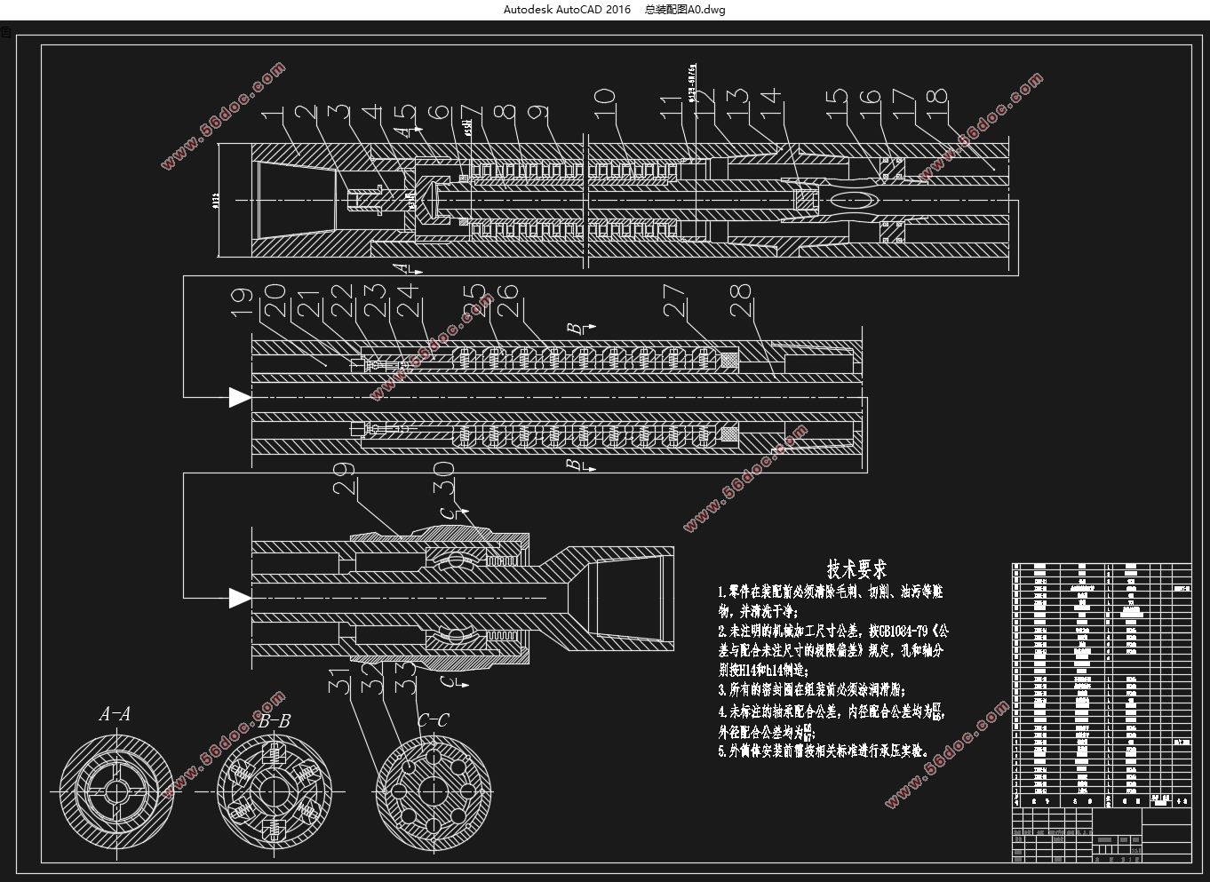
液力推进器有以下几大主要机构,分别是行程器,钻头,心轴和缸体。缸体作为主要零部件,前端连接钻头,中部主要包括行程器,缸体等主要零部件,该设备主要利用井中的泥浆,泥浆流入机构活塞中,对钻头产生额外的压力。
本文主要对液力推进器进行设计,在现有结构的基础上对其进行改进和完善,做到进一步的提高其工作效率,节省成本。
关键词:液力推进器、液压缸,设计
Abstract
The hydraulic thruster is a new type of downhole tool. Its main function is to convert the pressure drop of the drill bit into the WOB, and at the same time, it can also stabilize the WOB, improve the drilling speed and the service life of the drill bit; the hydraulic thruster especially The effect is particularly obvious in directional wells. It can be beneficial to overcome frictional resistance and apply a constant weight on bit to the drill bit. The hydraulic thruster can also protect the drill string against longitudinal and lateral vibration of the drill bit. As a new downhole tool, it can not only solve the problem that WOB is not easy to apply in directional wells and extended-reach wells, but also reduce vibration isolation. This can greatly improve the service life of the drilling tool. The hydraulic propeller mainly includes an upper joint, a piston, a cylinder body and a mandrel. The upper joint is connected with the drill collar, and the lower is connected with the cylinder body. The pressure drop generated by the flow of mud is mainly used to act on the piston to generate WOB. This paper mainly designs the hydraulic propeller, and improves and perfects it on the basis of the existing structure, so as to further improve its working efficiency and save the cost.
Keywords: hydraulic propeller, hydraulic cylinder, design
本文主要的设计参数:
钻压:7-9t;
排量:12-14L/s;
直径:172mm
驱动形式:泥浆驱动
使用位置:在水平段钻井

目 录
摘 要 I
Abstract II
目 录 III
1 绪论 5
2 总体方案设计 5
2.1 确定执行元件 5
2.2 分析系统工况 5
2.3 负载循环图和速度循环图的绘制 7
3 零部件方案设计 9
3.1油缸主参数的确定 9
3.1.1 液压缸的内径 9
3.1.2 活塞杆的直径 10
3.1.3液压缸缸体厚度计算 13
3.1.4 液压缸长度的确定 14
3.1.5 缸筒的加工要求 15
3.1.6法兰设计 15
3.1.7 (缸筒端部)法兰连接螺栓的强度计算 16
3.2 活塞的设计 17
3.3 导向套的设计与计算 18
3.4 端盖和缸底的设计与计算 20
3.5 缸体长度的确定 21
3.6 缓冲装置的设计 21
3.7 排气装置 21
3.8 密封件的选用 23
3.9 防尘圈 24
3.10 液压缸的安装连接结构 24
3.11心轴的设计 27
4 使用与操作 30
4.1 下井前检查 30
4.2 安装位置 30
4.3 钻压调节 30
4.4 操作方法 31
总 结 32
致 谢 33
参考文献 34
|