42t-33m门座式起重机整体与平衡梁结构参数化设计(含CAD图,SolidWorks三维图)(任务书,开题报告,论文说明书14000字,CAD图1张,SolidWorks三维图)
摘要
随着起重运输机械越来越广泛的应用于国民建设的各个领域,对起重机的设计也有了更深层次的要求,要求起重机的设计和制造能够快速广泛的适应市场。本文针对国内外港口起重机的发展现状,进行门座起重机的整体设计,然后利用SolidWorks三维建模软件建立门座起重机的平衡梁的模型,并通过VB实现模型的参数化,通过改变变量参数,来改变平衡梁的相应尺寸从而达到重建模型的效果。最后进行起重机的参数化结构装配,并利用ANSYS Workbench进行有限元分析。
本课题的特色在于通过调用SolidWorks内部的API函数对平衡梁参数化模型进行驱动,达到通过改变参数可以得到不同尺寸的平衡梁模型的目的,有效缩短设计制造周期;并成功通过有限元分析软件将起重机的三维建模与有限元分析紧密结合进行了初步尝试。
关键词:参数化;整体设计;三维建模;有限元分析;门座起重机
Abstract
With the lifting and transportation machinery more and more widely used in the various fields of national construction, the design of the crane also has a deeper level of requirements, the crane design and manufacturing can quickly and widely adapt to the market. This topic in view of the current situation of the development of port crane at home and abroad, the integral design of the portal crane, and then using the SolidWorks 3 d modeling software to establish the balance of the door crane beam model, and through the VB technology implementation model parameterization, by changing the parameters of the variable, to alter the balance beam size accordingly to achieve the effect of reconstruction model. Finally, the parameterized structure of the crane is assembled, and finite element analysis is carried out by using ANSYS Workbench.
The feature of this project is that the parametric model of the balance beam can be driven by using the API function inside SolidWorks, so that the balance beam models of different sizes can be obtained by changing the parameters, and the design and manufacturing cycle can be effectively shortened. Finally, a preliminary attempt is made to combine the 3d modeling of the crane with the finite element analysis by using the finite element analysis software.
Keywords: portal crane; Overall design; 3d modeling; The parameterized; Finite element analysis
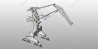
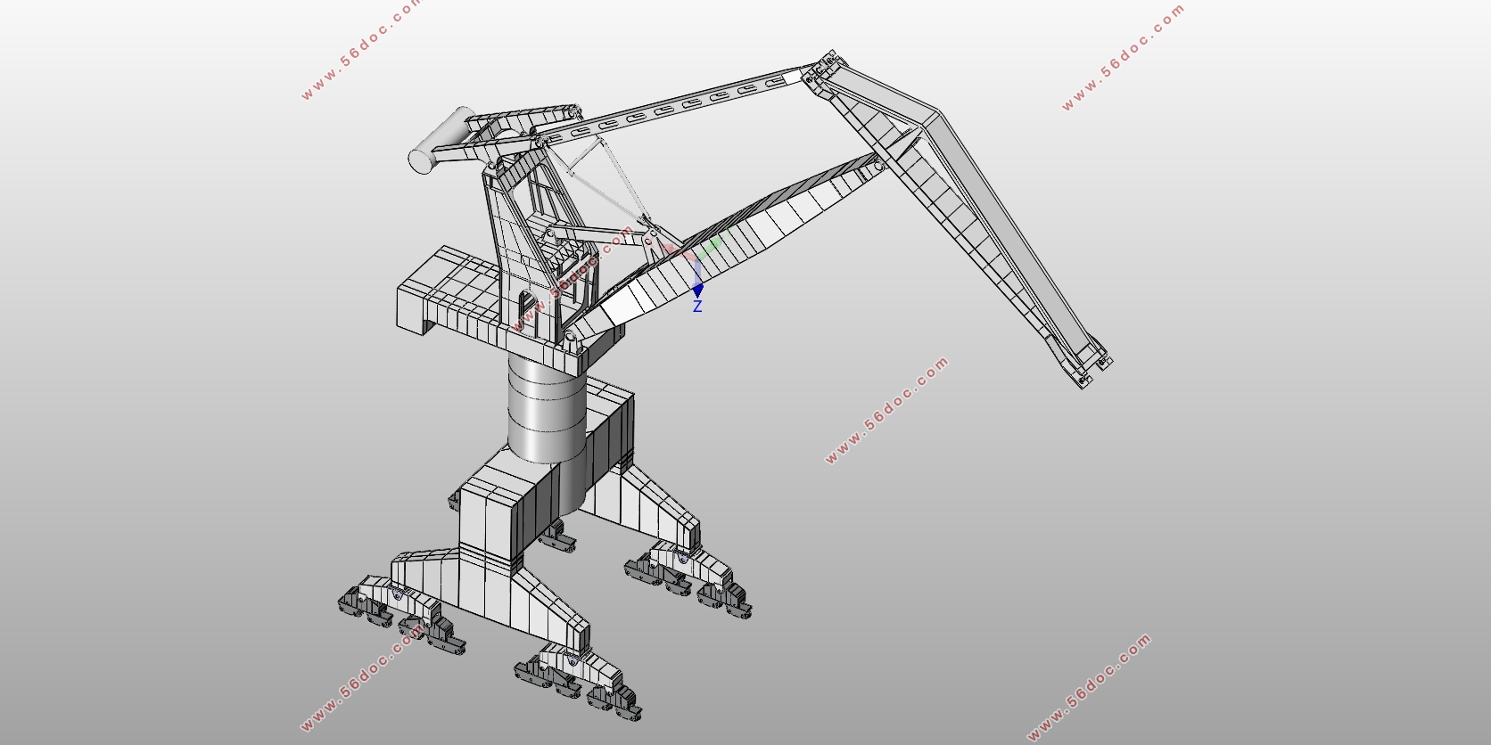
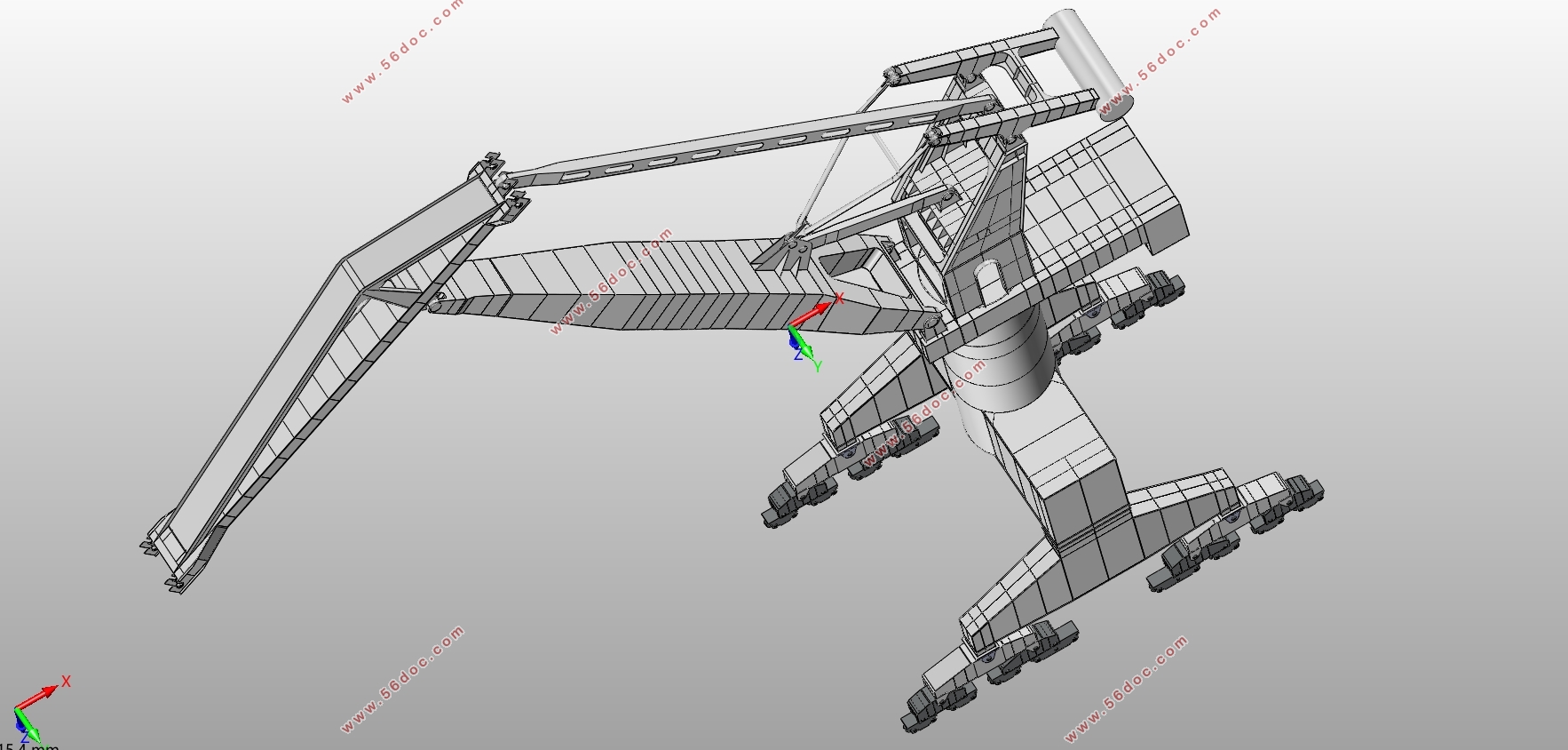
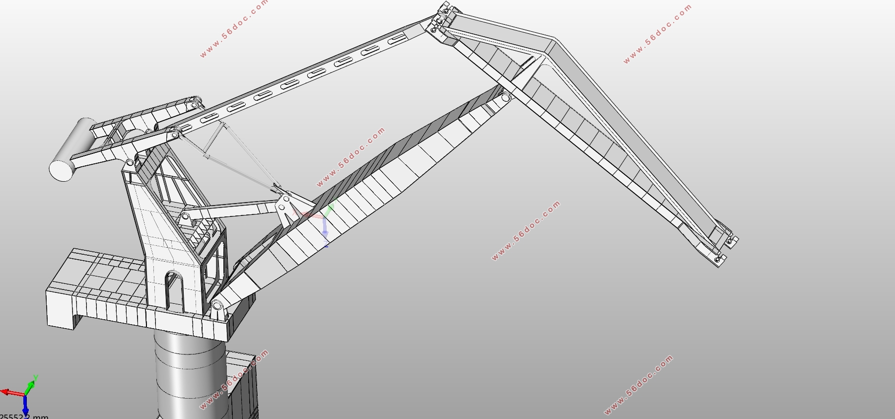
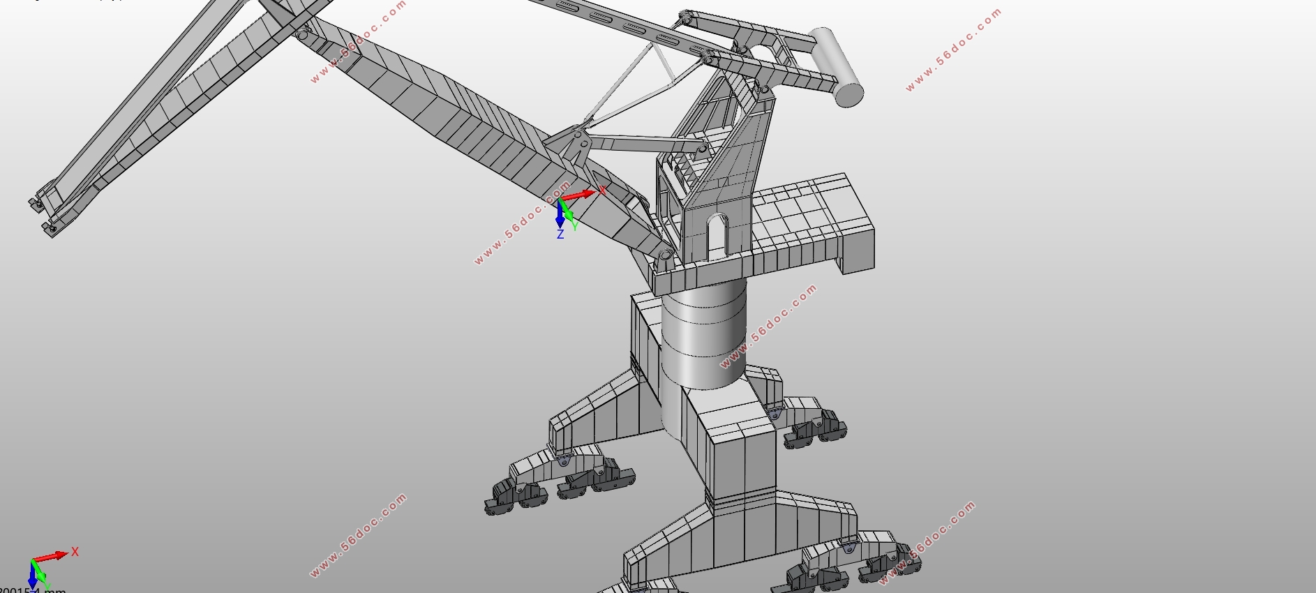
门座起重机主要包括上部旋转和下部运行两个部分,由变幅机构、起升机构、回转机构和运行机构等四大部分组成,通过这四个机构的协调工作来实现物品的起升和转移,并且根据实际工作需要,可以通过轨道将起重机整体从一个地点运行到另一个地点。
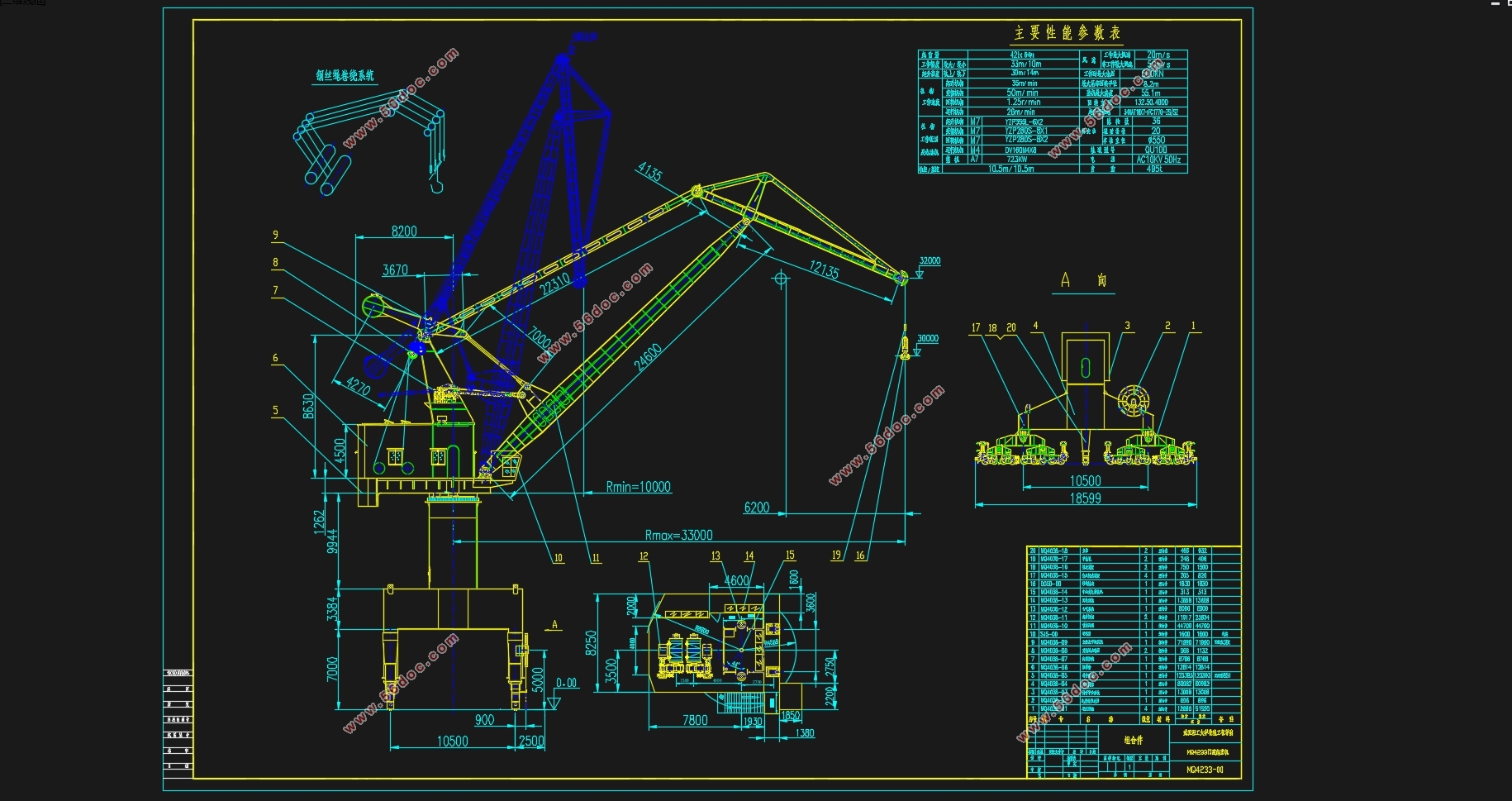
2.1主要设计参数
起重机的设计参数是起重机的工作性能指标,主要包括:
(1)起重量
起重量即为额定起重量,是起重机在正常工作条件下所能起升的最大净起重量。本课题的起重机 的取物装置采用的是吊钩,起重量为42t.
(2)起升高度和下降深度
起升高度是吊钩的最高位置到起重机支撑面的垂直距离;下降深度即起重机支撑面到吊钩的最低 工作位置的距离。本课题所用起重机的轨上高度为30m,轨下高度为14m。
(3)幅度
幅度代表了起重机的工作范围,是吊钩到转台回转中心线的距离。本课题的最大幅度是33m,最 小幅度是10m。
(4)尾部回转半径
尾部回转半径是活对重最外边缘到回转中心线的最大距离。本课题的尾部回转半径最大为8.2m。
(5)轨距和基距
轨距是起重机大车运行轨道中心线的距离,基距是下横梁和最大均衡梁连接绞轴之间的水平距离 。本课题的起重机的轨距为10.5m,基距为10.5m。
目录
第一章 绪论 1
1.1课题的研究目的和意义 1
1.2国内外研究现状分析 1
1.2.1国内研究现状 1
1.2.2国外研究现状 2
1.3课题的研究内容 2
第二章 门机总体设计 4
2.1主要设计参数 4
2.2 臂架系统结构尺寸 4
2.3全幅度水平落差校核 8
2.4全幅度水平速度校核 8
2.5吊重不平衡力矩校核 9
2.6杠杆活对重法臂架自重平衡系统 9
2.7平衡系统的校验 10
2.8数据汇总 12
第三章 平衡梁的结构 15
3.1起重机金属结构选型 15
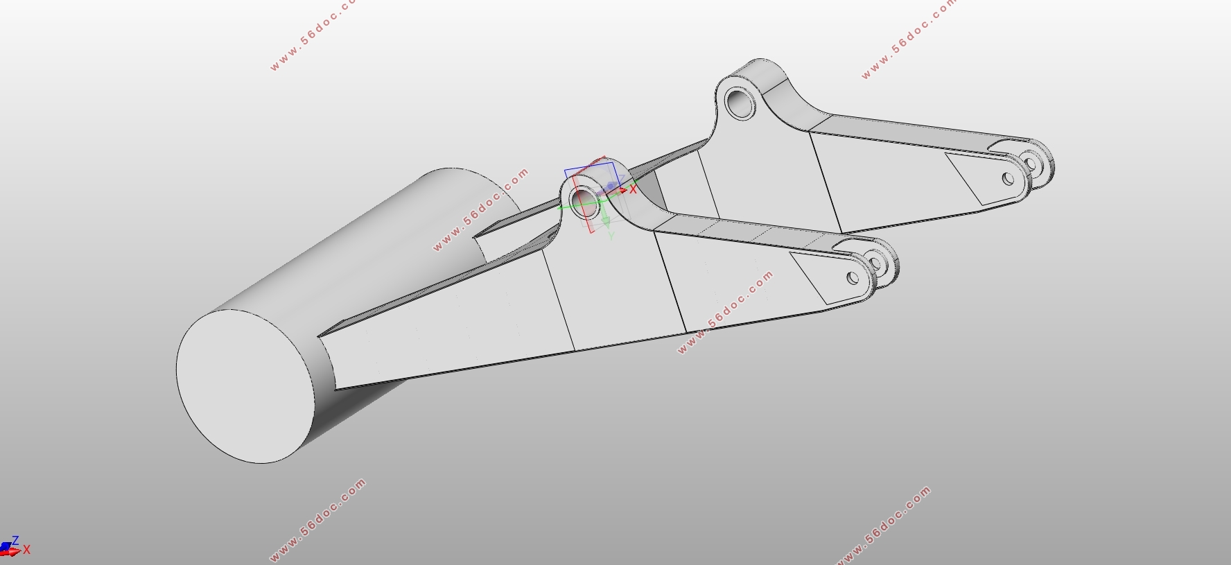
3.2平衡梁结构简介 15
3.2平衡梁简要受力分析 16
第四章 参数化模型建立与程序开发 17
4.1结构参数化模型建立 17
4.1.1建模工具——SolidWorks简介 17
4.1.2明确主要设计参数 17
4.1.3结构参数化模型建立 18
4.2结构参数化程序开发 21
4.2.1 VB简介 21
4.2.2基于VB的二次开发简介 21
4.2.3参数化开发 22
4.2.4参数化结果分析 29
第五章 有限元分析 32
5.1 有限元理论 32
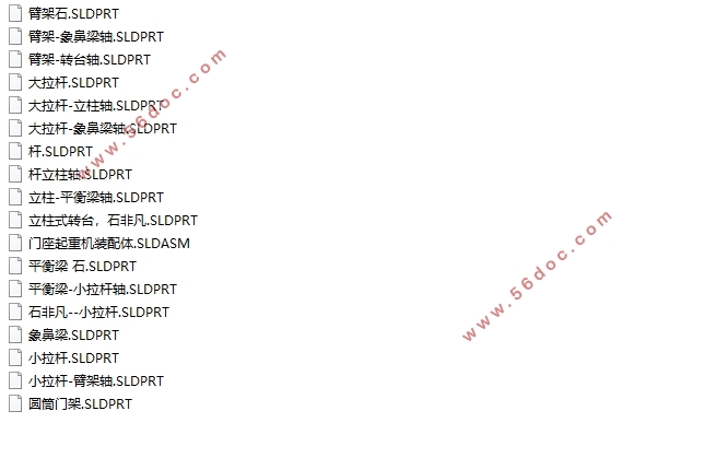
5.2模型装配 32
5.3有限元分析 33
5.3.1 材料特性 33
5.3.2划分网格 34
5.3.3添加载荷和施加约束 34
5.3.4结果分析 35
第六章 环保经济性分析 35
6.1设计成本分析 36
6.2优化方案简介 36
6.3环保经济性分析汇总 36
第七章 总结与展望 37
7.1工作总结 37
7.2难点及不足 37
7.3课题展望 37
致谢 38
参考文献 39
附录 40
|