玻璃基板切割后自动去额料装置设计(含CAD图,SolidWorks三维图)(任务书,开题报告,论文说明书14600字,CAD图12张,PDF图12张,SolidWorks三维图)
摘 要
近年来液晶技术发展迅速,越来越多带有液晶面板的产品已经成为人们日常生活中的必需品。为适应显示器使用量日益增加的需求,我们除了提高产品的功能与性能,还需要做到三点才能从竞争激烈的国内外市场中脱颖而出:提升产能和降低成本,同时保证产品品质来提高产品市场竞争力。向工业4.0迈进,实现更高程度的工业自动化显然是最佳的解决之道。
本文结合企业实际生产情况,应用机械设计、传感器等相关知识以及PLC控制理论,设计引入一种自动化机台来实现切割后额料的去除。机台能够模拟人手剥离额料的动作,并利用风刀机构吹出的压缩空气清除面板上的玻璃屑等杂质,以便提高后续工序的加工质量,减少不良品的产生。
关键词:液晶技术;切割;自动化;PLC;机构设计
Abstract
For the past few years, liquid crystal technology has developed rapidly, and more and more products with liquid crystal panels have become a necessity in People's Daily life. In order to adapt to the increasing demand for customers to monitor usage, we in addition to meet the high speed, high resolution, wide viewing angles corresponding requirements, such as still need to do at leastthreepoints toemerge from a competitive market at home and abroad, improve productivity and reduce the costs, and guarantee the product quality to enhance the competitiveness of product markets. The best solution is to move towards industry 4.0 and achieve higher levels of industrial automation.
In this paper, based on the actual production situation of enterprises, the application of mechanical design, sensors and other relevant knowledge and PLC control theory, the design introduces an automatic machine to realize the removal of the cutting post. The machine can simulate hands of person toremove the waste.In addition,it can blow off the chips of glass by using its wind knife,which is in order to improve the processing quality of the follow-up process and reduce the generation of defective products.
Keywords:Liquid crystal technology; Cutting; Automation; PLC; Mechanism design
摘 要 I
Abstract II
第1章 绪论 1
1.1论文研究背景及研究对象 1
1.1.1 论文的研究背景 1
1.1.2 论文的研究对象 2
1.2国内外现状 2
1.3论文工作的目的和意义 3
1.4论文的主要研究内容 3
第2章 自动去额料装置设计方案确定 5
2.1切割制程简介 5
2.2车间生产现况分析 5
2.3设计方案确定 6
第3章 自动去额料装置关键机构的设计 7
3.1零件材料的选择 7
3.2 AutoCAD二维图纸绘制 7
3.2.1推片及定位销 7
3.2.2风刀固定机构 8
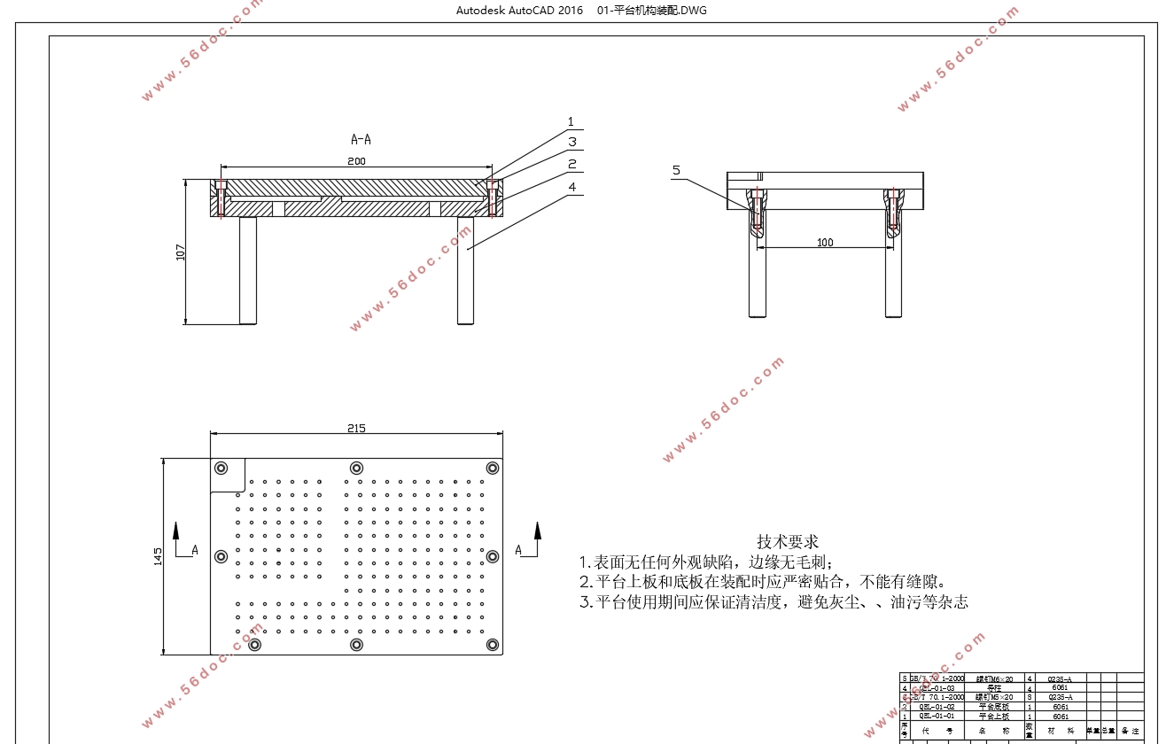
3.2.3平台 9
3.2.4气缸固定机构 11
3.2.5机台大底板 12
3.3 Solidworks三维建模 12
3.3.1 模拟手剥额料机构 13
3.3.2 风刀机构 13
3.4运动仿真 13
第4章 去额料装置自动控制的实现 15
4.1确定控制要求 15
4.2选择和确定I/O设备 16
4.2.1光电传感器 16
4.2.2 电磁阀 16
4.3 PLCI/O分配设计 18
4.3.1统计I/O点数并选择PLC型号 18
4.3.2 I/O端子的分配及接线图 18
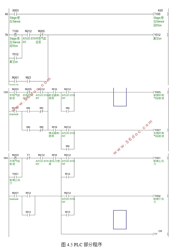
4.4 设计PLC控制程序 19
4.4.1手动操作 19
4.4.2自动运行 20
4.5 人机交互设计 21
4.5.1触摸屏型号选择 22
4.5.2人机界面设计 22
第5章 自动去额料装置总体设计 24
5.1额料收集 24
5.1.1漏斗 24
5.1.2集尘盒 24
5.2电控板 24
5.3 执行机构(气缸) 25
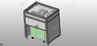
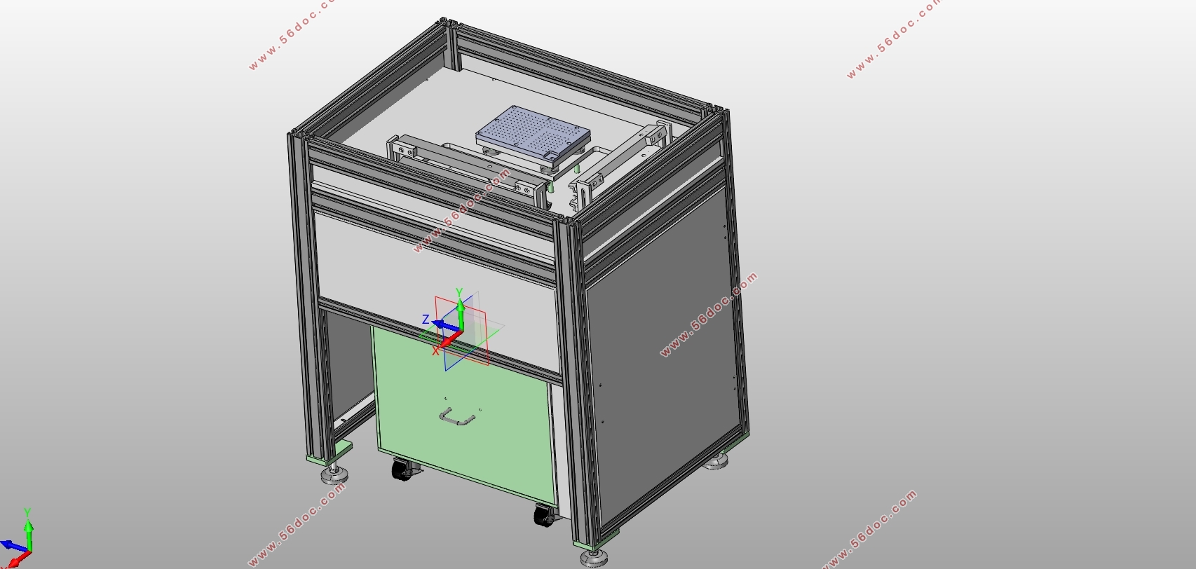
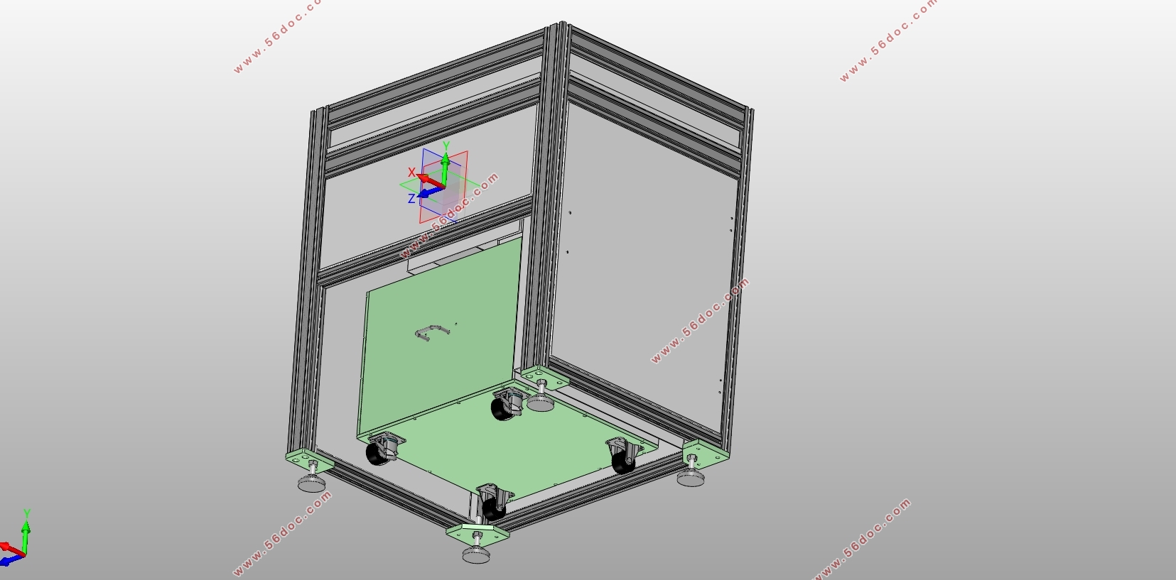
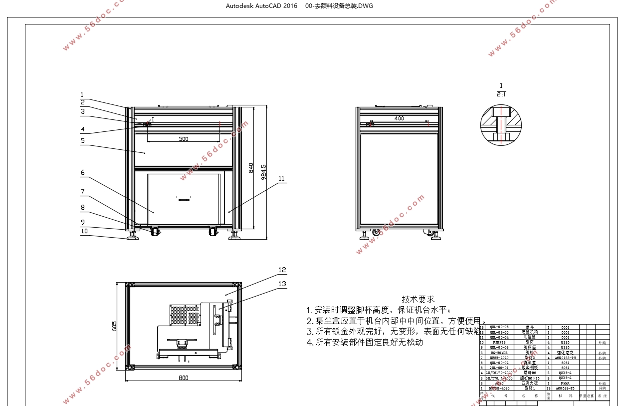
5.4 机台整体结构 26
第6章 设计成果应用 28
6.1 玻璃屑改善 28
6.2 生产节拍加快 28
6.3 线路刮伤改善 29
第7章 全文总结与展望 30
7.1 全文总结 30
7.2 论文工作展望 30
参考文献 31
致谢 32
|