重型剪刀叉式液压升降平台设计(含CAD零件图装配图)(论文说明书25000字,CAD图7张)
摘 要
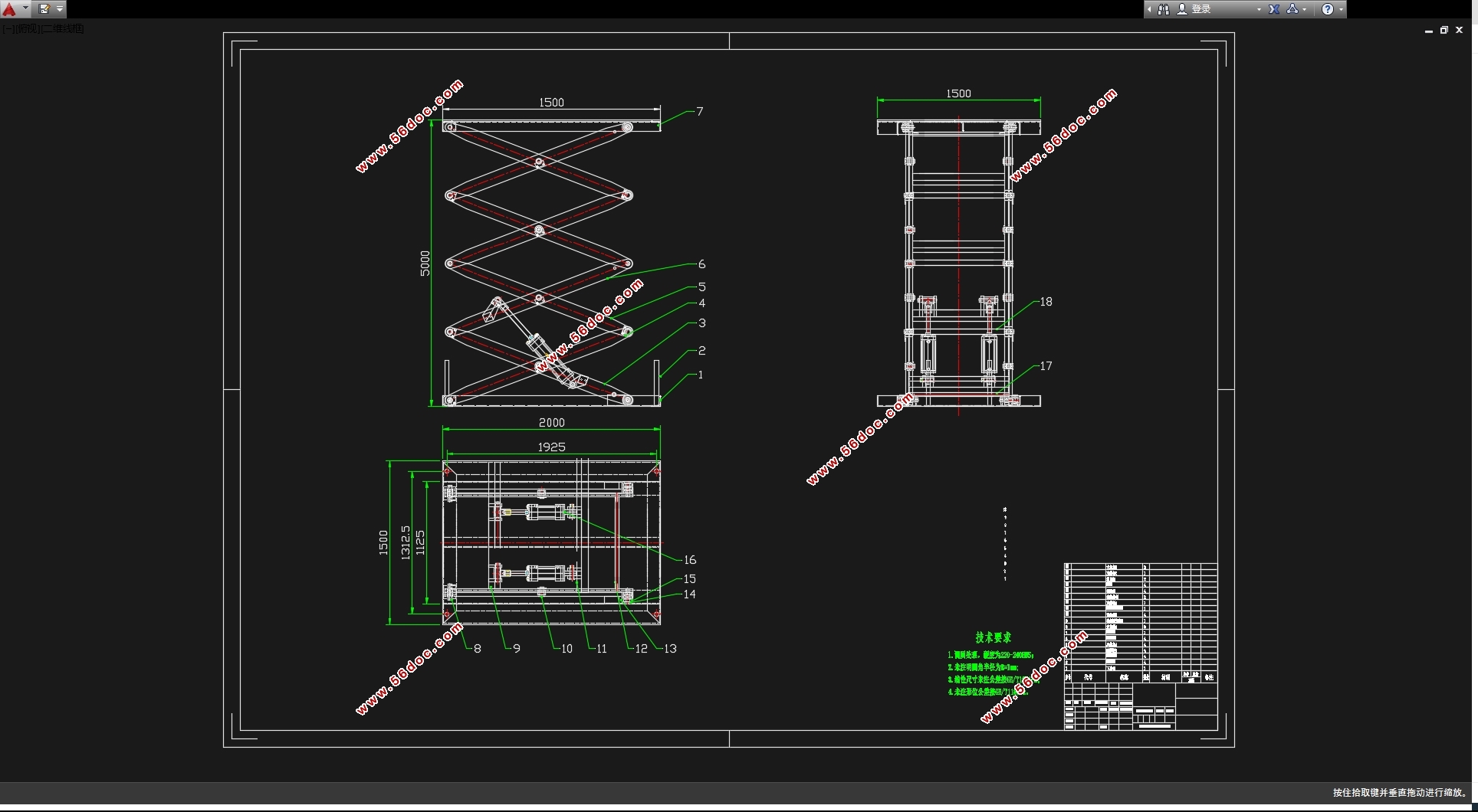
液压系统是剪叉式液压升降平台的驱动和控制部分,通过液压缸驱动剪叉改变幅度,完成升降任务,通过平衡阀、调速阀和溢流阀的控制作用,完成调速、保压、制动、平衡的功能。
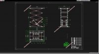
本次设计主要进行了升降平台功能特点分析求解,升降平台总体布局方案和主要性能参数确定,各机构和各部件的结构方案设计,主要控制方案设计,上、下台架机构、剪叉机构设计计算,整机稳定性、可靠性验算。根据实际需求拟采取如下:选择液压缸为动力,以剪叉式为传动形式,主体机构采用剪叉式结构设计。对剪叉式升降平台关键零部件进行设计计算与校核,经过验证能实现预期的设计目标和要求。
关键词:升降平台,液压升降,重型剪叉式,结构设计
Abstract
The hydraulic system serves as the driving and control component of the scissor hydraulic lifting platform, which changes the range through the hydraulic cylinder to complete the lifting task. The functions of speed regulation, pressure maintenance, braking, and balance are achieved through the control of the balance valve, speed regulating valve, and overflow valve.
This design mainly analyzes and solves the functional characteristics of the lifting platform, determines the overall layout scheme and main performance parameters of the lifting platform, designs the structure of each mechanism and component, designs the main control scheme, and calculates the design of the upper and lower frame mechanisms and scissor mechanisms, as well as the stability and reliability of the entire machine. Based on actual needs, the hydraulic cylinder is selected as the power source, and the scissor structure is adopted as the transmission form, with the main structure designed in a scissor style. The critical components of the scissor lifting platform are designed, calculated, and verified to achieve the expected design goals and requirements.
Key Words:The lifting platform,Hydraulic lifting,Heavy-duty scissor-type,Structural design.

目 录
摘 要 II
Abstract III
目 录 IV
第1章绪 论 7
1.1升降平台对于工业、农业、交通等领域都有重要的影响力与价值。 7
1.2升降平台国内研究发展情况 8
1.3 课题来源、选题的目的及意义 9
1.4主要研究内容及预期目标 9
第3章 剪叉式升降平台结构设计计算 14
3.1 升降机构的设计 14
3.1.1 升降机构形式的选择[1] 14
3.1.2 直接推动式升降机构 14
3.1.3 连杆组合式升降机构 14
3.2 升降平台的两种机构形式 17
3.3 通过对三种不同的液压缸布置方式的分析,我们可以更好地掌握升降平台的性能特点[3]。 17
3.3.1问题的提出 18
3.3.2三种方案的分析和比较 18
3.4 剪叉式升降平台结构分析 19
3.5 剪叉式升降平台的运动分析 21
3.6 剪叉式升降平台的动力分析 24
3.7 剪叉式升降平台参数的确定 25
3.7.1基本几何尺寸的确定 25
3.7.2 液压缸推力T及行程S的确定 26
3.8剪叉式升降平台的校核 26
3.8.1各铰接点的受力分析 26
3.8.2各铰接点销的选择与校核 29
3.8.确定和校核3个油缸的杆件尺寸,以确保它们能够正常工作。 29
3.9 强度校核 31
3.9.1 剪叉臂的强度校核 31
3.9.2 校核液压缸底架的横梁的强度,以确保其稳定性和可靠性。 33
3.10 轴的强度校核 36
3.10.1 校核内剪叉臂的固定端销轴的强度,以确保其可靠性。 36
3.10.2 检查液压缸缸体尾部销轴的强度,以确保其正常运行。 37
3.10.3 校核液压缸活塞杆头部支撑轴的结构强度,以确保其可靠性和可操作性。 37
第3章 液压传动系统的设计计算 39
4.1明确设计要求 制定基本方案[8] 39
4.2制定液压系统的基本方案 40
4.2.1确定液压执行元件的形式[10] 40
4.2.2 确定液压缸的类型[14] 41
4.2.3 确定液压缸的安装方式[15] 41
4.2.4 缸盖联接的类型[16] 41
4.2.重新设计液压执行部件的运动控制系统,以提高效率和可靠性。 42
4.2.6液压源系统 42
4.3确定液压系统的主要参数 43
4.3.1载荷的组成与计算: 43
4.3.2初选系统压力 45
4.3.3计算液压缸的主要结构尺寸 45
4.3.4确定液压泵的参数 47
4.3.5管道尺寸的确定 48
4.3.6油箱容量的确定[26] 49
3.四个液压缸的主要部件的结构、材料和技术要求都有所不同。 49
4.4.1缸体[27] 49
4.4.2活塞[28] 49
4.4.3活塞杆[30] 50
4.4.4活塞杆的导向、密封和防尘 51
4.4.5液压缸的排气装置[32] 52
4.4.6个液压缸的连接方式和大小如下: 52
4.5 本章小结 54
第4章 剪叉式升降平台结构设计的运动学分析 55
5.2 位移、速度及加速度分析 57
5.2.1主运动分析 57
5.2.2 位移曲线 58
5.2.3 速度曲线 59
5.2.4 加速度曲线 59
总结 61
参考文献 61
致谢 64
|