电器外壳塑件及其注塑成型模具的设计(含UG三维图)(论文说明书20000字,UG三维图)
摘 要
电器外壳塑件是外壳中的重要组成部分,要求塑件内表面平整光滑,无翘曲、皱折、裂纹等缺陷,周口部高度差不可过大,以保证零件与零件间的严密配合。塑件件的这些特点就决定了其成形过程的复杂性和工艺方案的多样性。
依靠传统的设计方法,对于处理这类问题已显得无能为力。随着注塑模具行业的发展,计算机模拟技术已成为改造传统的塑性成形工艺、提高模具设计能力的有力工具和关键技术。
本电器外壳塑件采用UG NX 5.0进行设计,利用UG软件创建模具的3D模型。在熟悉产品的结构、使用、储存、运输的前提下,合理选用塑料原材料,结合塑料原材料的各项性能,包括物理性能、机械性能、化学性能、光学性能,得到塑件的收缩率,选用合理的模具制造材料设计出相应的模具。设计中利用UG完成塑料模具的基本造型和标准件的加载。利用华塑CAE软件完成塑件的网格分析,在网格分析的基础上进行华塑CAE塑料注塑成型过程仿真集成分析,得到了一系列的重要参数,包括注塑量,注塑压力,注塑机的选型,密度分布,温度场的分布,锁模力等,模拟分析结果较为合理。
关键词:电器外壳 模具设计 UG NX 5.0 CAE模拟
Design and simulation of electrical enclosure plastic parts and injection molding mold
ABSTRACT
Electrical enclosure plastic parts were an important part of the housing, the inner parts demands that the piece be flat and smooth, no defect of warp, wrinkle and crack etc., and that the high-low deflection of its periphery not too big. These features of the piece make the forming process complicated and the processing plan various.
According to traditional design method, it seems incapable to deal with this kind of problem. With the development of plastic injection mold industry, computer simulation technology has become the transformation of traditional plastic forming processes, improve powerful tool and die design capabilities of key technologies.
The electrical enclosure plastic part was designed using UG NX 5.0, using UG software to create 3D models of the mold. Considering the structure of the product, using condition, storage requirement and transportation, the reasonable plastic raw material was selected. By studying the varies performance of these plastic raw materials, including physical properties, mechanical properties, chemical properties and optical properties, the shrinkage rate of the designed plastic parts was concluded. With the reasonable choice of mold manufacture materials, the corresponding mold was designed. The basic plastic mold shape and standard accessory loading was studied by using the UG tool. Using Huasu CAE software and the Huasu CAE-plastic injection molding process simulation of integrated analysis to complete the the grid analysis of the plastic parts, a series of important parameters were elicited, including injection quantity, injection pressure, injection molding machine selection, density distribution, the distribution of the temperature field and the clamping force. The results of simulation were more reasonable.
Key Words: Appliances shell; Mold design; UG NX 5.0; CAE simulation
目 录
摘 要 I
ABSTRACT II
目 录 III
第一章 文献综述 1
1.1 课题研究背景 1
1.2 注塑模具发展趋势 2
1.3 塑料模具 CAE 技术及发展趋势 3
1.4 课题的研究内容及意义 4
1.4.1 本设计的内容 4
1.4.2 本设计的目的和意义 4
第二章 电器外壳设计及网格分析 6
2.1 UG简介 6
2.2 塑件选材 7
2.2.1 改性PBT性质 7
2.2.2 改性PBT的应用 7
2.2.3 改性PBT工艺特点 7
2.3 塑件设计 8
2.3.1 塑件表面粗糙度 8
2.3.2 塑件的尺寸精度设计 8
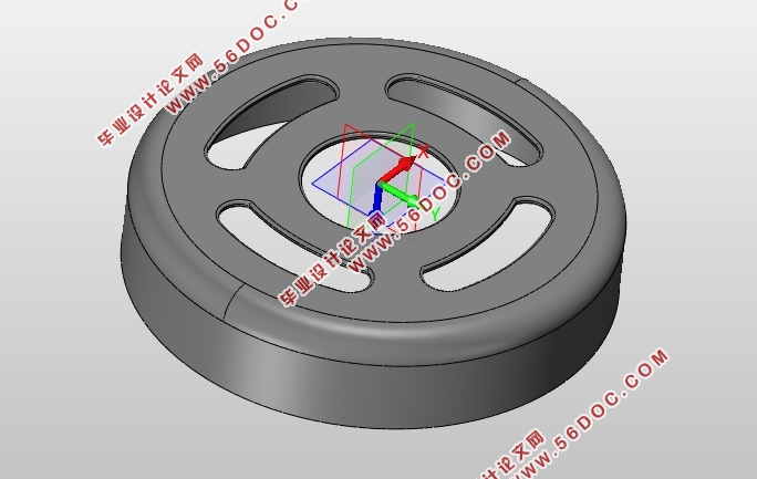
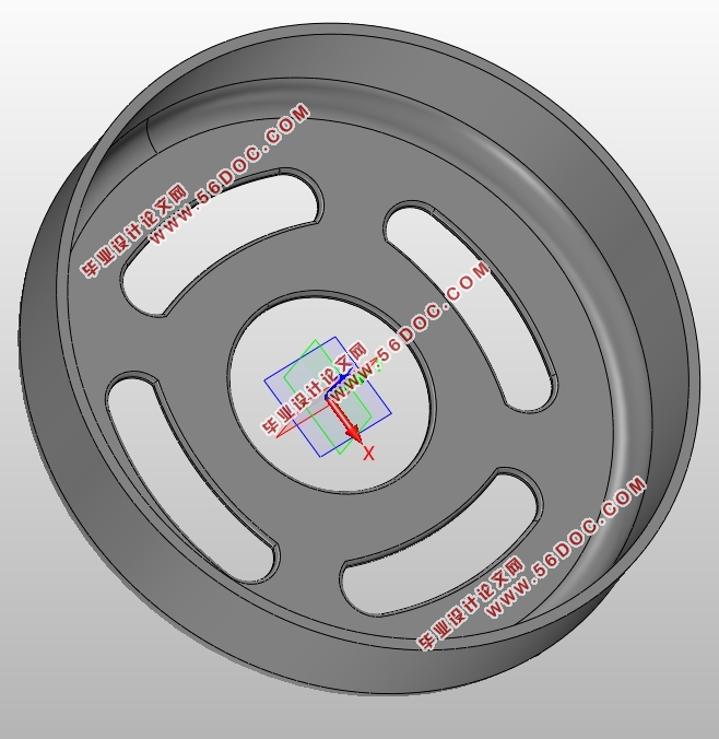
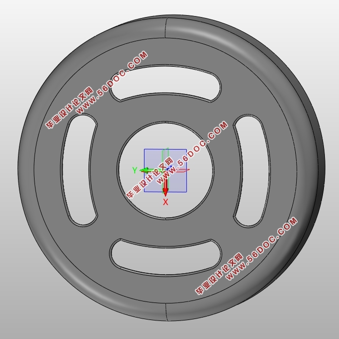
2.3.3 塑件绘制 8
2.4 塑件网格分析 10
2.4.1 华塑网格管理器 10
2.4.2 网格划分及修复 10
2.4.3 STL分析结果 11
第三章 电器外壳塑件注塑模具设计 13
3.1 模仁设计 13
3.1.1 模仁尺寸设计 13
3.1.2 模仁绘制 13
3.2 分型设计 15
3.2.1 创建分型线 15
3.2.2 创建分型面 16
3.2.3 创建补面 17
3.2.4 型芯、型腔设计 17
3.3 型腔布局 19
3.3.1 型腔数量 19
3.3.2 型腔排位 19
3.4 模架设计 20
3.4.1 模架选择 20
3.4.2 创建模架 22
3.5 创建避空位 24
3.5.1 创建模仁避空角腔体 24
3.5.2 创建动定模仁避空位 24
3.6 浇注系统设计 25
3.6.1 浇注系统设计应遵循以下原则 25
3.6.2 主流道设计 26
3.6.3 分流道设计 29
3.6.4 浇口设计 31
3.7 模具温度控制的设计 33
3.7.1 设计原则 33
3.7.2 水道尺寸设计 34
3.7.3 动模仁侧冷却水道设计 34
3.7.4 添加O型圈 35
3.7.5 螺旋管设计 36
3.8 排气系统 37
3.9 模具脱模系统设计 37
3.9.1 脱模系统的设计原则 37
3.9.2 顶针设计 38
3.9.3 添加支撑柱 39
3.9.4 添加限位钉 41
3.9.5 添加拉料杆 42
3.9.6 复位弹簧设计 44
3.10 塑件模具 45
3.10.1 模具零件选材 45
3.10.2 模具整体框架 46
第四章 电器外壳塑件注塑模具的CAE模拟 47
4.1 充模设计 47
4.1.1 HSCAE软件介绍 47
4.1.2 脱模方向设计 47
4.1.3 多型腔设计 47
4.1.4 定义进料口 48
4.1.5 设计流道 48
4.1.6 充模工艺条件 48
4.2 冷却设计 50
4.2.1 设计虚拟型腔 50
4.2.2 回路设计 50
4.2.3 冷却工艺 52
4.3 结果分析 54
4.3.1 制品信息 54
4.3.2 材料数据 55
4.3.3 工艺条件 56
4.3.4 充模分析结果 56
4.3.5 冷却分析结果 60
4.3.6 应力翘曲分析结果 63
第五章 结论与展望 64
5.1 结 论 64
5.2 展 望 64
参考文献 65
致 谢 66
|