зѓКѓЕМЯђБлМЗбЙж§дьФЃОпЩшМЦМАЪ§жЕФЃФт(КЌCADЭМ,UGШ§ЮЌЭМ)(ШЮЮёЪщ,ПЊЬтБЈИц,ТлЮФЫЕУїЪщ12000зж,CADЭМ8еХ,UGШ§ЮЌЭМ,ЖЏЛЗТецЪгЦЕ)
еЊвЊ
БОДЮБЯвЕЩшМЦЕФСуМўЪЧЦћГЕСуМўжаЕФзѓКѓЕМЯђБлЃЌИУСуМўЕФећЬхГпДчВЛДѓЃЌЯрЭЌГпДчЖрИіЩњВњЁЃИљОнСуМўНсЙЙЃЌОіЖЈВЩгУМЗбЙж§дьЙЄвеЩњВњФЃОпЃЌвдДЫРДЩшМЦЬиЪтЕФННзЂЯЕЭГЃЌвЛФЃСНМўЭЌЪБЩњВњСуМўЁЃЭЈЙ§AnyCastingШэМўЖдСуМўННзЂЯЕЭГЕФГфаЭМАФ§ЙЬЙ§ГЬНјааЗТецФЃФтЃЌЗжЮіж§МўПЩФмЛсВњЩњЕФШБЯнЃЌгХЛЏННзЂЯЕЭГНсЙЙЃЌгХЛЏЙЄвеВЮЪ§ЁЃ
ФЃОпгавЛИіаБЯђаЭаОЃЌаБГщаООрРыНЯГЄЃЌГщаОСІНЯДѓЃЌВЩгУСЫвКбЙВрГщаОЛњЙЙЃЌБЃжЄСЫСНИіаБаЭаОЭЌЪБЖЏзїЃЌЬсИпЩњВњаЇТЪЁЃгЩгкж§МўБэУцДцдкдВЛЁБэУцЃЌгавЛЖЈЕФЭтЙлвЊЧѓЃЌВЩгУЭЦИЫЭЦГіЛњЙЙЃЌЭЦГіЮЛжУОљЩшжУдкСїЕРЩЯЃЌвдБмУтЖдДжВкЖШВњЩњгАЯьЁЃ
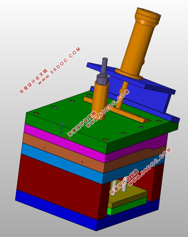
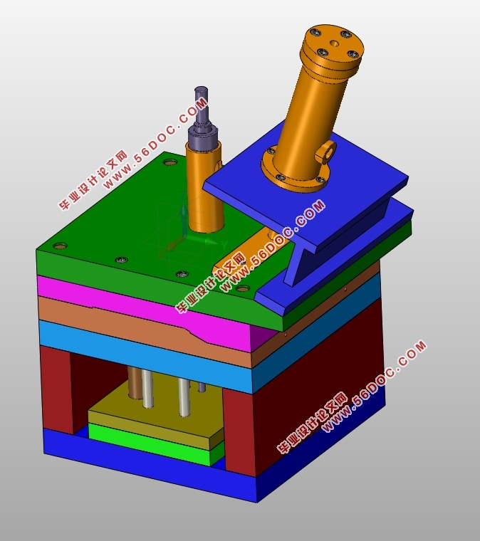
ЛљгкUGШ§ЮЌдьаЭШэМўЃЌЖдФЃОпИїВПЗжНсЙЙНјааЪЕЬхНЈФЃВЂАДеевЛЖЈзАХфЙиЯЕНјаазАХфЃЌШЛКѓЖдзАХфЬхНјааПЊКЯФЃдЫЖЏМАБЌеЈЭМЗТецЃЌбщжЄФЃОпНсЙЙЕФКЯРэадЁЃДгЖјЫѕЖЬМЗбЙж§дьВњЦЗПЊЗЂЪБМфЃЌНЕЕЭЩњВњГЩБОЃЌЬсИпВњЦЗжЪСПЃЌзюжеЬсИпВњЦЗЕФЪаГЁОКељСІЁЃ
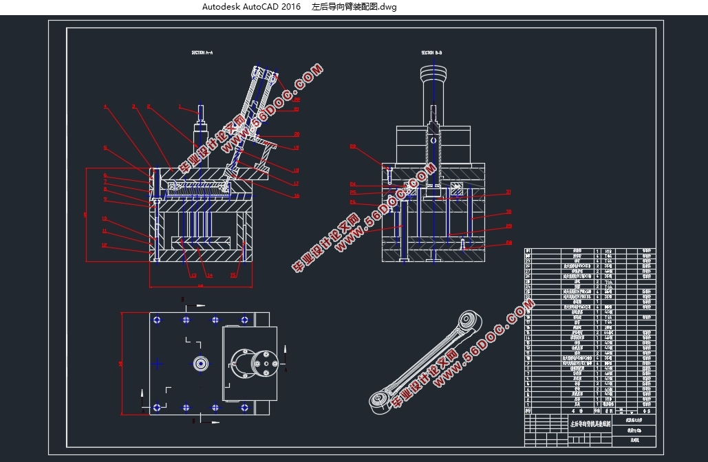
ЙиМќДЪЃКМЗбЙж§дьЃЛЦћГЕЬзЙмЃЛГфаЭМАФ§ЙЬЗТецЃЛЖЏЛЗТец
Abstract
The parts of this graduation design isthe parts of the car parts in the left rear guide arm, the overall size of the parts is not consistent. According to the structure of the parts, the design of special casting system is decided by the squeeze casting technology, and the two parts are produced simultaneously.The filling and solidification process of the casting system were simulated by AnyCasting software, and it can help to analyze the defects of the casting process, optimize the structure of the casting system was, and optimize the process parameters.
The mold has an inclined coreЃЌdue to the inclined core-pulling distance and high core pulling force, hydraulic pressure side core-pulling mechanism is adopted,so as to ensure the twoinclined core action at the same timeand to improve production efficiency.Because of the casting surface is the circular arc surface, and has a certain appearance requirements, the push rod pushing mechanism designed, the launch position are arranged in the flow channelin order to avoid the influence on the roughness.
Based on UG modeling software,the entity modeling of mold parts designed and assemble according to certain assembly relationships. Then make opening and closing movement and explosion diagram simulation to verify the rationality of the mold structure. So as to shorten the squeeze casting product development time, reduce production costs, improve productquality, and eventually improve the market competitiveness of the product.
Key Words: Squeeze casting;Left rear guide arm; The filling and solidification simulation; Animation simulation
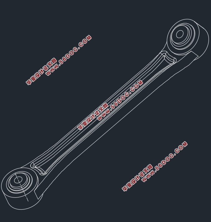
2.1ж§МўНсЙЙЗжЮі
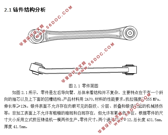
СуМўЪЧзѓКѓЕМЯђБлЃЌзмЬхРДПДНсЙЙВЂВЛИДдгЃЌжївЊЬиЕудкгкгавЛИіаБЯђЕФГщаОвдМАЩЯЯТУцЕФАМВлНсЙЙЁЃВњЦЗВФСЯгУ2A70ЃЌВФСЯЕФадФмвЊЧѓЃКПЙРЧПЖШ≥355 MPaЃЌЩьГЄТЪ≥12%ЁЃЖЭМўБэУцВЛдЪаэДцдкШтблПЩМћЕФСбЮЦЁЂЗжВуЁЂелЕўКЭЖЭдьв§Ц№ЕФЛњаЕЫ№ЩЫЕШЃЛЗЧМгЙЄБэУцЩЯВЛдЪаэгаДжВкЕФАЕАпКЭАзАпДцдкЃЌЕЋдЪаэгабѕЛЏЩЋДцдкЁЃИљОнСуМўЕФГпДчДѓаЁВЩгУСЂЪНМЗбЙж§дьЛњвЛФЃСНМўЩњВњЁЃСуМўГпДчЃКСНИіЭЈПзОљЮЊΦ12ЃЌзмГЄЖШ431.5mmЃЌКёЖШ41.5mmЁЃ
2.2МЗбЙж§дьЙЄвеВЮЪ§ЕФбЁдё
2.2.1ГфаЭЫйЖШ
ГфаЭЫйЖШвЛАуЪЧЫЕКЯН№вКдкЕЭбЙж§дьЧщПіЯТЃЌНјШыВЂЬюТњаЭЧЛЪБЕФСїЖЏЫйЖШЁЃЫцзХГфаЭЗНЪНЕФВЛЭЌЃЌЫќЕФГфаЭЫйЖШВњЩњЕФгАЯьвВЪЧВЛЭЌЕФЁЃ
ГфаЭЫйЖШШчЙћЙ§ЕЭЃЌКЯН№вКЛсВњЩњКёКёЕФвЛВуНсПЧВуЃЌЪЙГфаЭКЭж§дьЮоЗЈЫГРћНјааЃЌж§МўЛЙЛсВњЩњЫѕПзЁЂЫѕЫЩКЭРфИєЕШДѓСПЕФЮЪЬтЁЃ
ГфаЭЫйЖШШчЙћЙ§ИпЃЌФЃОпМфЯЖгжБШНЯаЁЃЌаЭЧЛФкЕФЦјЬхОЭВЛЛсдкгаЯоЕФЪБМфФкХХГіЃЌОЭЛсдьГЩОэЦјЯжЯѓЃЌвВЛсГіЯжЦјПзЁЂеыПзЕШШБЯнЁЃШчЙћФЃОпМфЯЖНЯДѓЃЌКЯН№вКОЭгаПЩФмХчГіРДЃЌДгЖјв§Ц№ШЫЩэЪТЙЪЛђепЛ№джЃЌЩѕжСКмПЩФмЪЙж§МўБЈЗЯЁЃ
злКЯПМТЧИїжжвђЫивдКѓЃЌГѕВНПМТЧГфаЭЫйЖШбЁШЁЮЊ10cm/sЁЃ


ФПТМ
еЊвЊ I
Abstract II
Ек1еТаїТл 1
1.1 МЗбЙж§дьМАЦфЬиЕу 1
1.2 МЗбЙж§дьЙЄвеЕФЗЂеЙ 2
1.3 МЗбЙж§дьЩшБИЕФЗЂеЙ 2
1.4ПЮЬтбаОПФПЕФвтвхМАФкШн 3
1.4.1 ПЮЬтбаОПФПЕФвтвх 3
1.4.2 ПЮЬтбаОПжївЊФкШн 3
Ек2еТГЩаЭЗНАИШЗЖЈ 4
2.1 ж§МўНсЙЙЗжЮі 4
2.2 МЗбЙж§дьЙЄвеВЮЪ§ЕФбЁдё 4
2.2.1 ГфаЭЫйЖШ 4
2.2.2 ННзЂЮТЖШ 5
2.2.3 ФЃОпдЄШШЮТЖШ 5
2.3 ЗжаЭУцЕФбЁдё 6
2.4 аЭаОаЭЧЛХХВМЗНЪНШЗЖЈ 7
2.5 ННзЂЯЕЭГЕФбЁдё 7
2.6 ХХвчЯЕЭГЕФЩшМЦ 7
Ек3еТвКЖЭЛњЕФбЁдё 8
3.1 вКЖЭЛњЕФЗжРр 8
3.2 зюДѓзЂЩфСПШЗЖЈ 9
3.3 бЙж§ЛњЕФбЁдё 9
3.4 ЫјФЃСІаЃКЫ 9
Ек4еТЛљгкAnyCasting ШэМўЕФЪ§жЕФЃФтЙ§ГЬ 11
4.1 AnyCasting МђНщ 11
4.2 Ш§ЮЌЪЕЬхНЈФЃ 11
4.3 ЧАДІРэЙ§ГЬ 12
4.4 ФЃФтдЫЫуЙ§ГЬ 16
4.5 КѓДІРэЙ§ГЬ 17
4.6 ФЃФтНсЙћЗжЮі 18
Ек5еТФЃОпНсЙЙЩшМЦ 19
5.1 ВрЯђГщаОЛњЙЙЕФЩшМЦ 19
5.1.1 ВрЯђГщаОЛњЙЙЕФЗжРр 19
5.1.2 ГщаОСІЕФМЦЫу 19
5.1.3 ГщаООрШЗЖЈ 20
5.2 ЭЦГіЛњЙЙЕФЩшМЦ 20
5.2.1 ЭЦГіЛњЙЙЕФЗжРрМАбЁдё 20
5.2.2 ЭЦГіВПЮЛЕФбЁдё 21
5.3 ФЃМмЕФШЗЖЈ 22
5.3.1 ФЃОпИїВПЗжГпДчШЗЖЈ 22
5.3.2 ФЃМмИїГпДчаЃКЫ 22
5.4 ФЃОпНсЙЙМАЙЄзїдРэ 22
5.4.1 ФЃОпНсЙЙ 22
5.4.2 ФЃОпЙЄзїдРэ 23
5.5 ФЃОпБЈМлЗжЮі 25
Ек6еТЛљгк3D MAXШэМўЕФФЃОпЖЏЛЗТец 26
змНс 28
жТаЛ 29
ВЮПМЮФЯз 30
|