角接支座冲压工艺与模具设计(含CAD零件图装配图,UG三维图)(任务书,开题报告,论文说明书10500字,CAD图17张,UG三维图)
摘要
随着时代发展和工业的进步,冷冲压技术也有了迅速的发展。现今,各个国家拥有且已经用于实践生产的冲压工艺有精密冲压,软模成型,无模多点成形,高效精密冲压技术,爆炸和电磁等高能成形,超塑性成形以及冷挤压技术等。这批先进技术工艺在实践生产运用中已获得并将继续创造出更多的经济收益。冲压制品在这个时代的日常生活和工业发展等各个地方都已经得到了充分的应用,机械业中更加突出。大部分机械外壳都是冲压制成,要想提高产品性能,需要的是高标准的冲压模具、成型工艺、冲压性能和冲压制品的设计等各种条件。本次毕业设计的出发点就是立于冲压成型的如此广泛应用之上的。
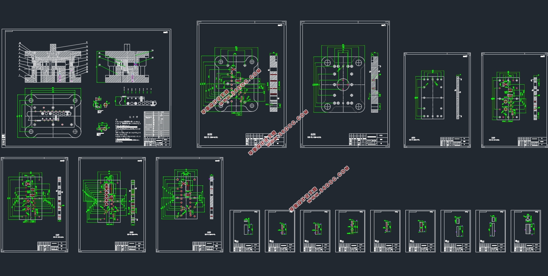
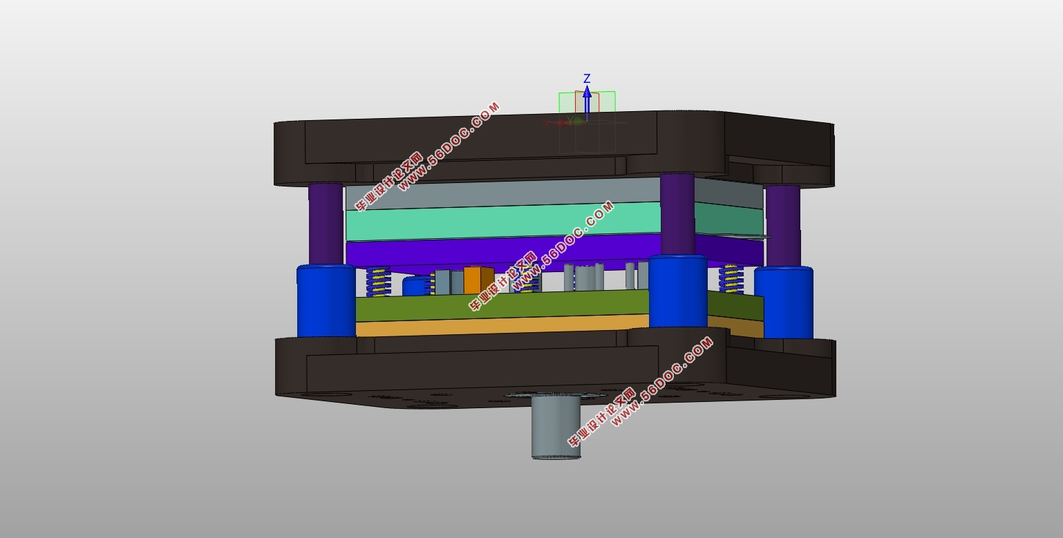
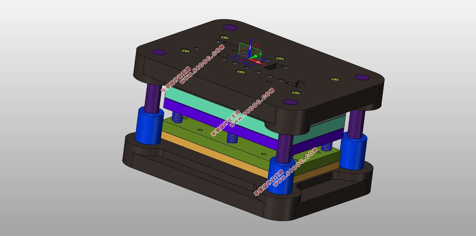
根据给出的角接支座尺寸模型完成其冲压工艺与模具设计是本次毕业设计主要任务。经过各种方案的比照,此次设计拟定使用连续模结构,在模具中安排冲孔、翻边、弯曲、落料等工位。此次毕业设计经过具体的零件分析和精度要求进行冲压工艺分析,提出合理的冲压工艺方案。从工艺可行性这个角度思考分析,画出零件展开图,计算毛胚尺寸以及设计了排样图。结合工艺计算结果,对凸、凹模和凸模固定板等模具主要零部件进行具体设计,以及角接支座的连续模设计。设计模具总体结构时,应该考虑包括上下模座、垫板、导柱导套、固定板、卸料板、卸料板弹钉等各个零部件的设计与选用。学习并使用Auto CAD2007软件绘制此次角接支座连续模模具的装配图和零件图。
关键词:连续模;冲孔;落料;弯曲;翻边
Abstract
With the development of the times and the progress of industry, cold stamping technology has also been rapid development. Today, the countries have been used and has been used for the production of stamping processes are precision stamping, soft mold molding, moldless forming, efficient precision stamping technology, explosion and electromagnetic high-energy forming, superplastic forming and cold extrusion technology.This batch of advanced technology in the practice of production has been obtained and will continue to create more economic benefits. Stamping products in this era of daily life and industrial development and other places have been fully applied, the machinery industry is more prominent. Most of the mechanical shell is made of stamping, in order to improve product performance, the need for high-quality stamping die, molding process, stamping performance and stamping products such as design conditions. The starting point of this graduation design is based on the extensive application of stamping.
According to the given angle bearing model to complete the stamping process and mold design is the main task of this graduation design. After a variety of programs, the design of the use of continuous mold structure, in the mold design punching, flanging, bending, blanking and other stations. The graduation design through the specific parts analysis and precision requirements for stamping process analysis, put forward a reasonable stamping process program. According to the feasibility analysis of the process, draw the parts to expand the map, design the layout. Combined with the calculation results of the process, the convex, die and punch fixed plate and other mold parts of the specific design, as well as the corner of the continuous design of the bearing. The design of the overall structure of the mold, including the upper and lower mold base, guide column guide sleeve, plate, fixed plate, the material board, the discharge plate, the discharge plate and so on the design and selection. Learn and use Auto CAD2007 software to draw the assembly of the cradle bearing die and assembly drawings.
Key wards: progressive die; blank; pierce; bend
零件的材料分析
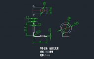
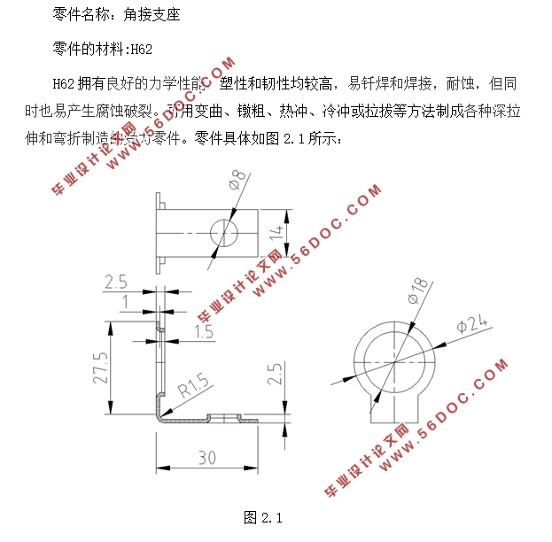
零件名称:角接支座
零件的材料:H62
H62拥有良好的力学性能,塑性和韧性均较高,易钎焊和焊接,耐蚀,但同时也易产生腐蚀破裂。可用变曲、镦粗、热冲、冷冲或拉拔等方法制成各种深拉伸和弯折制造的受力零件。
2.2 零件工艺分析
根据图中给出的条件,这个工件形状较为简单,要求精度一般。零件尺寸公差按IT14级选取。冲压该零件需要4道基本工序分别为冲孔、翻边、弯曲、落料。因此可以考虑以下三种方案:
方案一:冲孔--翻边--折弯--落料连续冲压,采用连续模生产。
方案二:先落料,再冲孔、再翻边、再折弯,采用单工序模生产。
方案二虽然模具结构简单,但因为有四道工序,需要多套模具才能完成零件加工。从而导致了生产效率很低,很难用于零件大批量的生产。同时因为要制造多套模具,必定导致其成本突增,不符合经济效益。此外,这样做的话精度也很难满足孔中心与边缘距离的尺寸公差。因此不采用此方案。
方案一中连续模由多工位组成,每个不同工位按照各自顺序独立完成其相应的加工任务。在冲床的一次行程中完成一系列的不同的冲压加工。冲床送料机在每次行程完成之后按照一个固定的步距将材料向前移动,可以在一副模具上完成我们所需的冲孔翻边弯曲落料4个工序。
通过上述对比我们不难发现,采用方案一的级进模设计,更加适合我们这次毕业设计的要求。


目 录
第1章 绪论 1
1.1 选题的意义与目的 1
1.3 研究现状 1
1.4 设计思路 2
第2章 角接支座的冲压工艺分析 3
2.1 零件的材料分析 3
2.2 零件工艺分析 3
2.3 毛坯的尺寸计算 4
2.4 排样设计 7
2.4.1 排样原则 7
2.4.2 搭边值的确定 7
2.4.3 载体设计 8
2.5 本章小结 10
第3章 角接支座连续模的工艺计算 11
3.1 压力的计算 11
3.1.1 冲裁力的计算 11
3.1.2 弯曲力的计算 13
3.1.3 翻边力的计算 13
3.2 压力中心计算 14
3.3 各主要零件尺寸的计算 14
3.3.1 凹模厚度 14
3.3.2 凸模固定板的选用与厚度 17
3.3.3 垫板的选用与厚度 17
3.3.4 卸料零件的计算 19
3.4 冲裁间隙的确定 19
3.5 冲孔刃口尺寸计算 21
3.6 落料刃口尺寸计算 22
3.7 冲裁刃口高度 23
3.8弯曲部分刃口尺寸的计算 23
3.9弯曲部分工作尺寸的计算 24
3.10 翻边凸、凹模尺寸计算 25
3.11 本章小结 26
第4章 连续模的总体结构以及零部件设计与选用 27
4.1 模具主要零部件的设计 27
4.1.1 冲裁凸、凹模的设计 27
4.1.2 卸料板的设计 29
4.1.3其他零部件的设计 29
4.2 模架的设计 29
4.3冲床选用 30
4.3.1 冲压设备的选择依据 30
4.3.1 压力机的选择 30
4.4模具的总体结构设计 30
4.5模具的总体结构设计 32
总结 33
致谢 34
参考文献 35
|