铁齿成型切边模具设计(含CAD装配图)(任务书,论文说明书13000字,CAD图2张)
摘 要
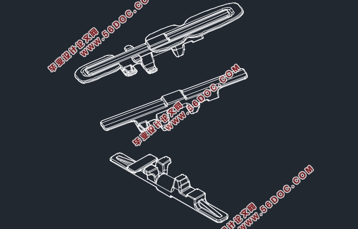
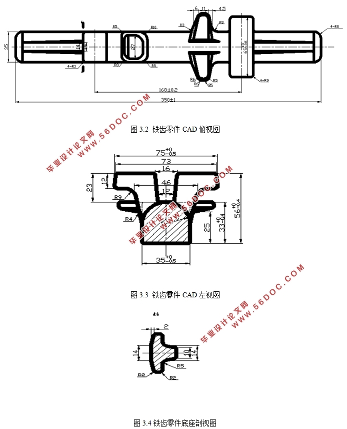
橡胶履带与其他传动装置相比具有结构简单、装置重量轻、传动过程中震动小、噪声小等优点,从而广泛应用于工程领域、农用领域和雪地领域等领域中。铁齿作为橡胶履带中得传动件,在橡胶履带的传动过程中起到承受各种应力、传递以及导向启动力和横向支撑的作用。由于铁齿通常采用锻造成形方式,来满足其对力学性能较高的要求,在终锻后的零件周围必然会出现飞边结构,因此在铁齿锻造工艺之后的切边工艺也成为铁齿最终成形的关键工艺之一。
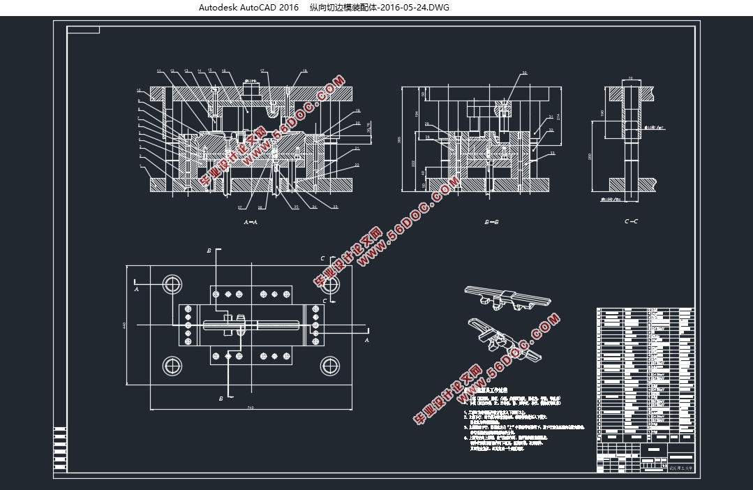
本文首先对于铁齿零件进行了介绍,接着综述了国内外切边技术的发展过程以及切边技术与有限元分析技术相结合的现状。然后主要针对终锻后铁齿的飞边结构进行切边模具的设计以及后续的利用有限元工具对设计得到的模具结构进行分析。首先通过铁齿CAD零件图运用ProE软件设计出铁齿零件的三维模型,然后通过查阅各种近年论文设计出铁齿的切边采用热模锻方式以及设计两套分别切横向和纵向飞边的模具结构,接着还是运用ProE软件成形设计的凸凹模三维结构,随后将设计好的凸凹模结构以及零件结构导入deform-3D软件中进行有限元模拟分析,验证所设计的切边模具的可行性,在deform-3D分析之后根据设计的凸凹模结构通过查阅表格选择出合适的模架结构和其他辅助零件,最后运用CAD绘图软件完成模具装配图以及零件图的绘制并撰写论文完成整个铁齿切边模具的设计。
关键词:铁齿;飞边;切边模;有限元;热模锻
Abstract
Compared to other transmission devices, rubber track has some advantages,for example simple structure, light weight, vibration in the process of transmission is small, the noise is low, therefore it has been widely used in the field of construction machinery, agricultural machinery and machinery be used in snow. The iron tooth is used as a transmission element in the rubber track, which can bear all kinds of stress, transfer and guide the starting force and as the transverse support during the transmission process of the rubber track. Due to the iron teeth usually made by forging way to meet its requirement of high mechanical properties, eventually forged parts around will appear flash structure, thus, the cutting edge technology has become one of the key processes of the gear teeth’s final forming.
Firstly, the paper introduces the iron tooth parts, and then summarizes the development process of the cutting edge technology at home and abroad as well as the current situation of the combination of the cutting edge technology and the finite element analysis technology. Mainly aimed at the design of trimming die for the flying edge structure after the final forging and using the finite element tool to analyze the structure of the mold. First, based on the parts diagram in CAD, use the ProE software to design the three-dimensional model of iron teeth. Then decide to cut the flying edge by hot die forming and designed two sets to cut transversely and longitudinally flying edge through accessing to a variety of thesis. Next put the die structures and part structure into deform-3D software to verify whether the die structures could work. After the analysis of DEFORM-3D, according to the design of the die structures, can select a suitable mold structure and other auxiliary parts through a lookup table. Finally use CAD drawing software to complete the mold assembly drawing and parts drawing, and then write papers of the design of the iron tooth cutting edge die.
Key Words:iron tooth;flying edge;cutting-side die ;finite element analysis;hot die forming

目 录
第1章 绪论 1
1.1 选题的目的和意义 1
1.2国内外研究现状 3
1.3 课题研究的主要内容 4
1.4 课题具体操作步奏 4
第二章 铁齿零件切边模具设计 6
2.1 切边过程设计 6
2.2 切边模具参数要求 7
第三章三维建模 8
3.1铁齿零件三维模型建立 8
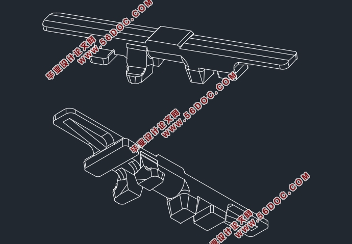
3.2 带横向飞边的铁齿零件三维模型建立 13
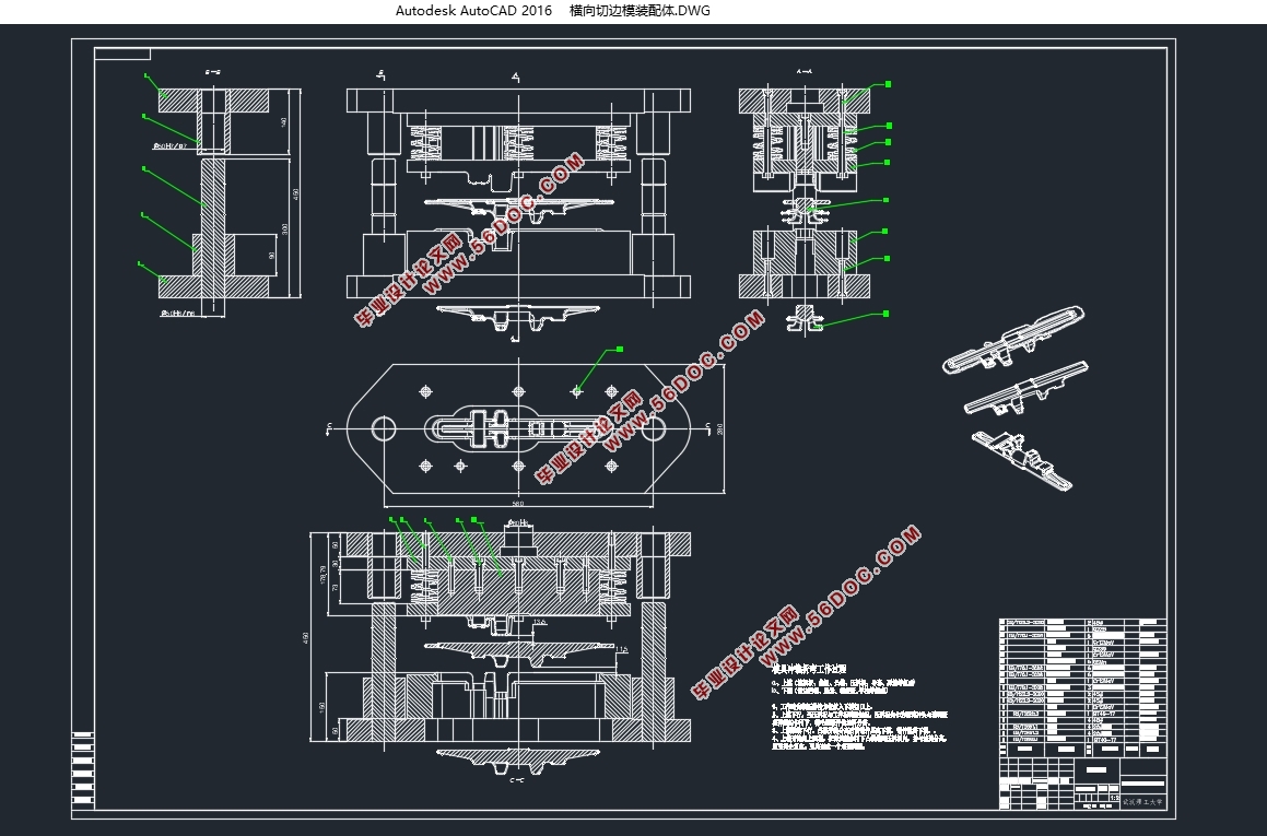
3.3 横向飞边切除模具的三维造型 13
3.4 本章小结 18
第四章有限元分析及优化模具 19
4.1仿真模型的建立 19
4.2 模具边界条件的设定 20
4.2.1 铁齿切边仿真基本参数设置 20
4.2.2 模具磨损准则的选择 22
4.2.3 模拟仿真 23
4.3本章小结 25
第五章模具尺寸设计 27
5.1 横向切边模具尺寸设计 27
5.1.1 模架选取 27
5.1.2 导柱及导套选取 28
5.1.3 垫板选取 29
5.2 纵向切边模具尺寸设计 30
5.2.1 模架选取 30
5.2.2 垫板选取 30
5.2.3 导柱及导套选取 30
5.2.4 垫块选取 31
5.2.5 导板选取 31
5.2.5 固定板选取 31
第六章模具工作原理 32
6.1 横向切边模具工作原理 32
6.2纵向切边模具工作原理 32
参考文献 34
致 谢 36
|