ЛљгкPLCМгШШТЏЮТЖШПижЦЯЕЭГЕФЩшМЦ(КЌCADНгЯпЭМЬнаЮЭМ)
РДдДЃК56doc.com зЪСЯБрКХЃК5D22221 зЪСЯЕШМЖЃКЁяЁяЁяЁяЁя %E8%B5%84%E6%96%99%E7%BC%96%E5%8F%B7%EF%BC%9A5D22221
зЪСЯвдЭјвГНщЩмЕФЮЊзМ,ЯТдиКѓВЛЛсгаЫЎгЁ.зЪСЯНіЙЉбЇЯАВЮПМжЎгУ. Ум БЃ Лн Аяжњ
зЪСЯНщЩм
ЛљгкPLCМгШШТЏЮТЖШПижЦЯЕЭГЕФЩшМЦ(КЌCADНгЯпЭМЬнаЮЭМ)(ТлЮФЫЕУїЪщ15000зж,ЭтЮФЗвы,CADЭМ6еХ)
еЊ вЊ
БОЮФжївЊНщЩмСЫЙЄвЕЮТЖШПижЦЕФЗЂеЙЧАОАЁЂS7-200ЯЕСаPLCЕФЛљБОжЊЪЖвдМАЙјТЏЮТЖШПижЦЯЕЭГЕФЙЄзїСїГЬЁЂЛљБОдРэКЭзщГЩНсЙЙЁЃЭЈЙ§ЖдЙјТЏЮТЖШПижЦЯЕЭГЩшМЦвЊЧѓЕФЗжЮіЃЌИјГіЙјТЏЮТЖШПижЦЯЕЭГЕФI/OПкЗжХфБэКЭЯЕЭГдРэЭМВЂЧввдПЩБрГЬПижЦЦї(PLC)ЮЊКЫаФЃЌИљОнЯЕЭГЕФПижЦвЊЧѓРћгУSTEP 7БрГЬШэМўЩшМЦЯЕЭГЕФЬнаЮЭМЁЃИУЯЕЭГвдЕчШШЙјТЏМгШШЙмЮЊБЛПиЖдЯѓЃЌЙјТЏЫЎЮТЮЊБЛПиВЮЪ§ЭЌЪБМцЙЫЙјТЏФкбЙСІМАЫЎЮЛЕШЬѕМўЃЌвдPLCЮЊПижЦЦїЃЌЙјТЏМгШШЙмЭЈЕчЪБМфЮЊПижЦВЮЪ§ЩшМЦСЫвЛИіЮТЖШПижЦЯЕЭГЁЃЦфжаЕїгУСЫЮїУХзгЙЋЫОPLCжаздДјЕФPIDФЃПщЃЌвдИќМђНрИќЗНБуЕФЗНЗЈЭъГЩСЫЙјТЏЮТЖШЕФздЖЏПижЦЩшМЦЁЃБОЮФДгЯЕЭГЕФЙЄзїдРэЁЂЯЕЭГгВМўбЁаЭЁЂЯЕЭГШэМўБрГЬвдМАзщЬЌМрПиЛУцЩшМЦЕШЗНУцНјааВћЪіЁЃ
ЙиМќДЪЃК ЕчШШЙјТЏЃЛЮТЖШПижЦЃЛPLCЃЛPIDЃЛЙЬЬЌМЬЕчЦї
Design of temperature control system based on PLC heater
Abstract
This article focuses on the industrial development prospects of temperature control, basic knowledge of S7-200 series PLC as well as the boiler temperature control system made up of work processes, principles, and structure.Through the analysis of boiler temperature control system design, I/O port allocation table of temperature control system of the boiler,system schematics and a programmable logic controller (PLC) as the core, according to the control system requires the use of STEP 7 programming software system design of ladder diagram.The system to electric boiler heating tubes to a charged object, parameters of boiler water temperature to be controlled both the pressure and the water level in the boiler and other conditions, the PLC controller, boiler heating power parameter design of a temperature control system for control.Which is called the Siemens PLC comes with PID modules, and a more concise and more convenient way to complete the automatic control system design of the boiler temperature. This paper described the working principle of the system, system hardware selection, system software programming and configuration of the monitor screen design.
Keywords ЃК Electric boiler; Temperature control; PLC; PID; Solid State Relays

ФП ТМ
еЊ вЊ i
Abstract ii
1 аїТл 1
1.1 ПЮЬтБГОАМАвтвх 1
1.2 ЙњФкЭтбаОПЯжзД 1
1.3 БОЮФбаОПФкШн 2
2 ЮТЖШПижЦЯЕЭГЩшМЦ 4
2.1 ЮТЖШПижЦЯЕЭГЙЄзїдРэ 4
2.2 PIDПижЦМАВЮЪ§ећЖЈ 4
2.2.1 PIDПижЦдРэ 4
2.2.2 PIDВЮЪ§ЕФећЖЈ 6
3 ЯЕЭГгВМўЩшМЦ 8
3.1 PLCЕФВњЩњКЭЬиЕу 8
3.1.1 PLCЕФВњЩњгыгІгУ 8
3.1.2 PLCЕФЬиЕу 8
3.2 PLCПижЦЯЕЭГЩшМЦЕФЛљБОддђКЭВНжш 9
3.2.1 PLCПижЦЯЕЭГЩшМЦЕФЛљБОддђ 9
3.2.2 PLCПижЦЯЕЭГЩшМЦЕФвЛАуВНжш 9
3.3 ЯЕЭГећЬхЩшМЦЗНАИ 10
3.4 PLCбЁаЭ 11
3.4.1 PLCЕФжїЛњФЃПщ 11
3.4.2 PLCЕФI/OРЉеЙФЃПщ 12
3.4.3 PLCЕФбЁдё 12
3.5 ДЋИаЦїбЁаЭ 12
3.5.1 ЮТЖШДЋИаЦїбЁаЭ 12
3.5.2 PT100ЮТЖШБфЫЭЦїбЁаЭ 13
3.5.3 бЙСІДЋИаЦїбЁаЭ 14
3.5.4 вКЮЛДЋИаЦїбЁаЭ 14
3.6 ЙЬЬЌМЬЕчЦї 14
3.6.1 ЙЬЬЌМЬЕчЦїЕФдРэЗжЮі 14
3.6.2 ЙЬЬЌМЬЕчЦїЕФзщГЩ 15
3.6.3 ЙЬЬЌМЬЕчЦїЕФгХШБЕу 15
3.7 Ъ§ТыЙм 16
3.8 ЯЕЭГЙЄзїСїГЬМАгВМўНгЯп 17
3.8.1 ЯЕЭГЙЄзїСїГЬ 17
3.8.3 ЯЕЭГжїЕчТЗЭМ 17
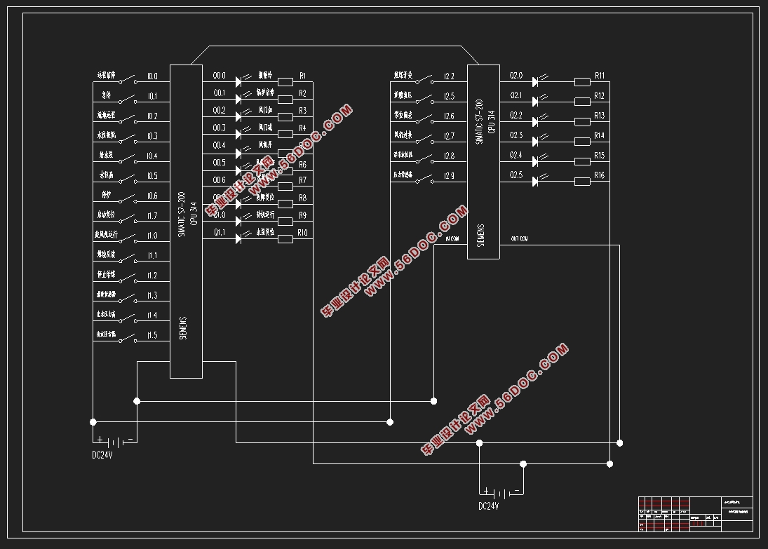
3.8.4 ЯЕЭГПижЦЕчТЗЭМ 18
3.8.5 PLCгВМўСЌНгЭМ 18
3.8.6 I/OЖЫПкЗжХф 19
4 ШэМўЩшМЦ 21
4.1 жїГЬађСїГЬЭМ 21
4.2 PIDПижЦЦїЕФВЮЪ§ећЖЈ 21
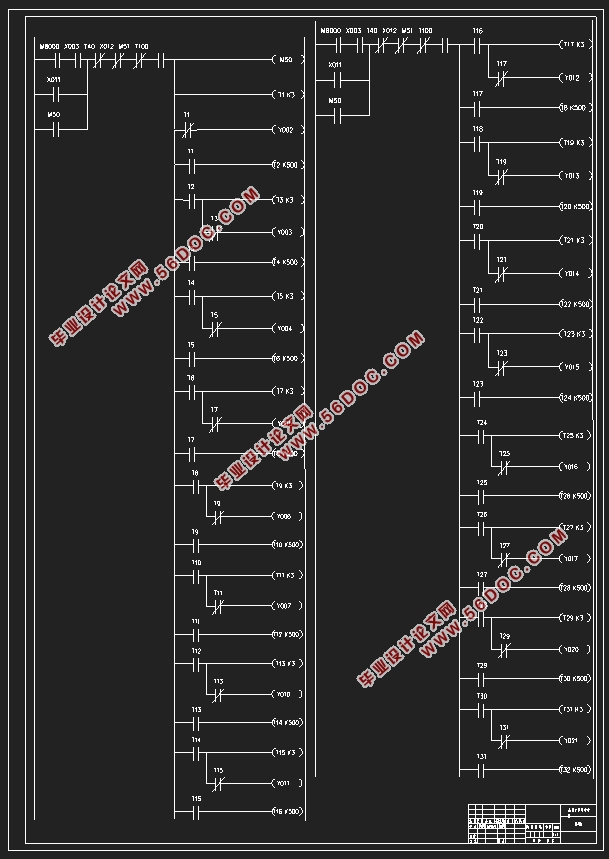
4.3 PLCГЬађЬнаЮЭМЩшМЦ 26
5 ШЫЛњНчУцЩшМЦ 36
5.1 зщЬЌШэМўЛљДЁ 36
5.1.1 зщЬЌЖЈвх 36
5.1.2 зщЬЌЭѕШэМўЕФЬиЕу 36
5.1.3 зщЬЌЭѕШэМўЗТецЕФЛљБОЗНЗЈ 36
5.2 зщЬЌБфСПЕФНЈСЂМАЩшБИСЌНг 37
5.2.1 аТНЈЯюФП 37
5.2.1 аТНЈЩшБИ 37
5.2.3 аТНЈБфСП 38
5.2.4 БфСПгыPLCЕФДЋЪф 39
5.3 ДДНЈзщЬЌЛУц 41
5.3.1 аТНЈжїЛУц 41
5.3.2 аТНЈPIDВЮЪ§ЩшЖЈДАПк 41
5.3.3 аТНЈЪЕЪБЧњЯп 42
5.3.4 аТНЈРњЪЗЧњЯп 42
5.3.5 аТНЈБЈОЏДАПк 43
6 ЯЕЭГЗТецМАВтЪд 44
6.1 ЯЕЭГдЫаа 44
6.2 дЫааНсЙћ 44
6.2.1 ВЮЪ§ЩшЖЈЛУц 44
6.2.2 ЪЕЪБЧїЪЦЧњЯп 45
6.2.3 РњЪЗЧїЪЦЧњЯп 45
6.2.4 БЈОЏДАПк 46
НсЪјгя 47
ИНТМ1 дДГЬађ 48
ИНТМ2 зщЬЌЭМ 62
ВЮПМЮФЯз 58
ЭтЮФзЪСЯ 61
жаЮФвыЮФ 68
жТаЛ 73
|