煤矿排水控制系统PLC控制与组态(含CAD接线图梯形图)(论文说明书22000字,外文翻译,CAD图5张)
摘 要
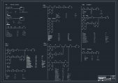
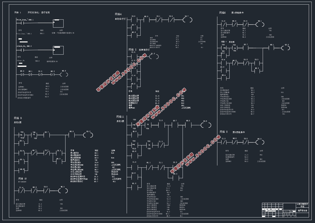
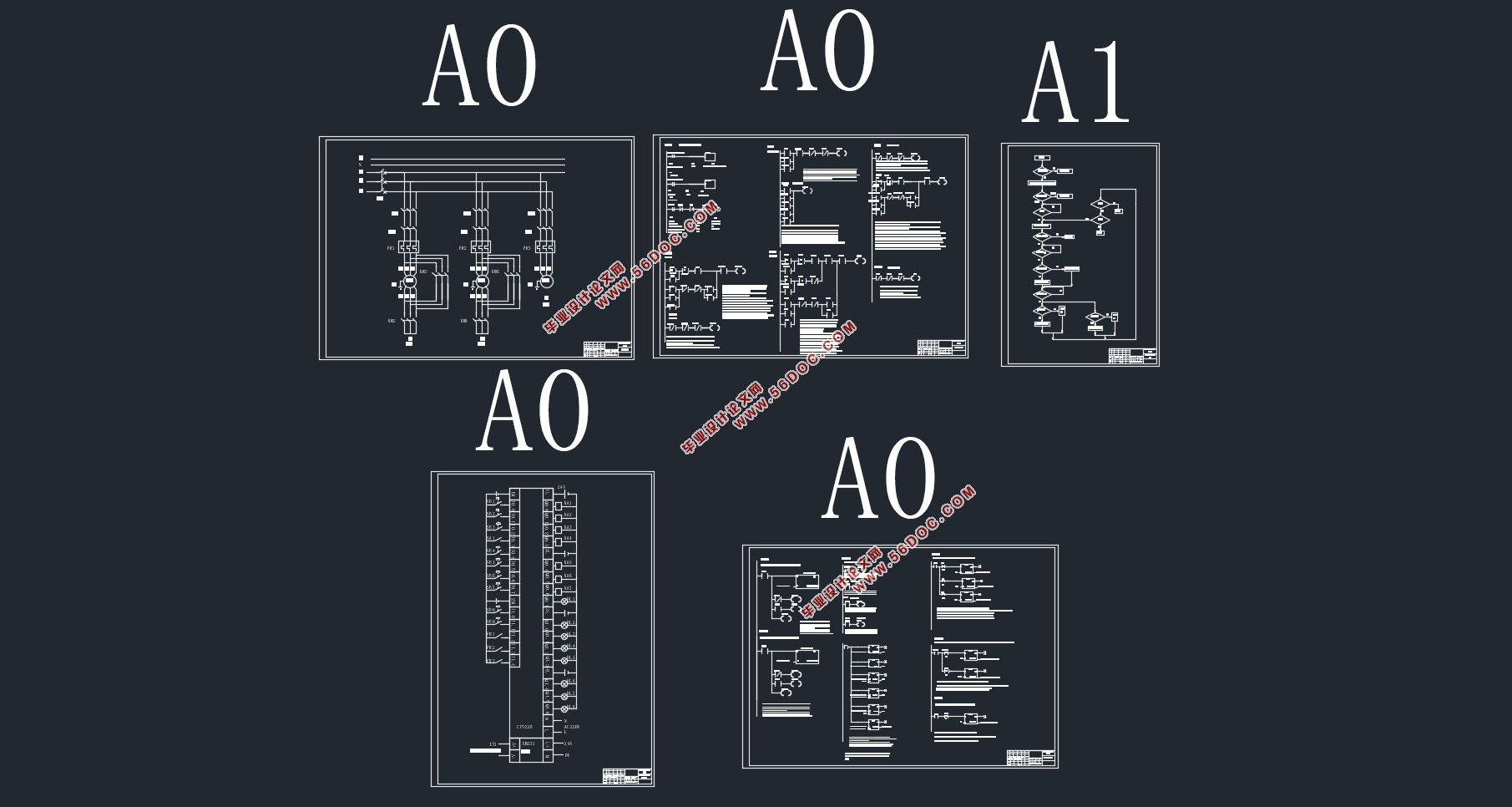
本设计是丰裕煤矿排水控制系统PLC控制与组态,采用西门子公司的S7-200小型PLC为控制核心,外加组态软件MCGS为上位机,结合各种传感器(例如水位传感器,压力传感器,温度传感器,流量传感器等),通过三台水泵完成排水自动控制。首先分析控制要求,进行了总体设计,然后进行了硬件设计,选择了PLC,设计了主电路和控制电路,分配了PLC的输入和输出,设计了PLC的输入和输出接线图,然后进行了软件设计,编制了控制程序流程图,编写了梯形图和语句表程序,最后使用MCGS进行了组态设计,监控排水系统运行情况,进行报警处理、参数设定、报表处理、实时和历史曲线显示、实时和历史报表查询等,做到有故障及时发现并尽早处理。
关键词:排水;梯形图;组态软件
PLC Control and Configuration of Fengyu Coal Mine Drainage Control System
Abstract
This design is the PLC control and configuration of Fengyu coal mine drainage control system, using S7-200 Small PLC of Siemens company as the control core, plus configuration software MCGS as the upper computer, combined with various sensors (such as water level sensor, pressure sensor, temperature sensor, flow sensor, etc.), through three pumps to complete the drainage automatic control. First, the control requirements are analyzed, the overall design is carried out, then the hardware design is carried out, the PLC is selected, the main circuit and control circuit are designed, the input and output of PLC are allocated, the input and output wiring diagram of PLC is designed, then the software design is carried out, the control program flow chart is compiled, the ladder diagram and statement table program are compiled, and finally the configuration design is carried out with MCGs, Monitor the operation of the drainage system, carry out alarm processing, parameter setting, report processing, real-time and historical curve display, real-time and historical report query, etc., so as to find out the fault in time and deal with it as soon as possible.
Key words: drainage; ladder diagram; configuration software
目 录
摘 要 i
Abstract ii
1 绪论 1
1.1 选题依据及意义 1
1.2 国内外现状研究 1
1.3 具体工作要求 2
1.3.1 软件分析和编写 2
1.3.2 硬件电路设计 2
2 可编程序控制器(PLC)的概况 3
2.1 PLC的产生和特点及其发展动向 3
2.1.1 PLC的产生 3
2.1.2 PLC的定义 4
2.1.3 PLC的特点 4
2.1.4 PLC的发展趋势 6
2.2 PLC 的系统结构和基本工作原理 7
2.2.1 PLC的系统结构 7
2.2.2 PLC的基本工作原理 9
2.2.3 PLC的主要功能 10
2.2.4 PLC 的应用设计步骤 11
3 总体设计 12
3.1 控制分析 12
3.2 方案设计 12
4 硬件设计 14
4.1电路设计 14
4.1.1主电路设计 14
4.1.2 控制电路图 16
4.2 PLC接线图 17
4.3 硬件选型 19
4.3.1 PLC型号的选择 19
4.3.2 压力传感器选型 19
4.3.3 流量传感器 21
4.3.4 中间继电器选型 22
4.3.5 水泵 23
4.3.6 交流接触器选型 24
4.3.7 热继电器选型 25
4.3.8 按钮开关选型 26
4.3.9 电源指示灯选型 27
4.4 PLC I/O表 28
4.5 电器清单 29
4.6 仪表电源箱 30
4.7其他 31
4.7.1母线系统 31
4.7.2现场I/O箱 31
4.7.3端子 32
5 程序设计 33
5.1编程软件STEP7--Micro/WIN概述 33
5.1.1 STEP7-Micro/WIN简单介绍 33
5.1.2 梯形图语言特点 34
5.1.3 STEP7-Micro/WIN参数设置(通讯设置) 35
5.2 控制流程图 37
5.3 PLC梯形图程序 39
6 组态设计 50
6.1 通讯定义 50
6.2 变量连接 51
6.3 组态画面 53
7 系统测试和仿真 56
结 论 63
参考文献 64
外文文献 66
英文原文 66
中文译文 76
致 谢 84
|