四自由度机械手臂的结构及控制系统设计(含CAD梯形图装配图)(论文说明书17000字,外文翻译,CAD图6张)
摘 要
随着工业快速发展,机械手在机械加工制造、装配及包装等自动生产线上得到普遍应用。机械手是一种能模仿实现人手部分功能,并能按编写程序进行搬运物料或抓取工件、操作工具等的装置;其对推动工业自动化生产发展起着重要作用。
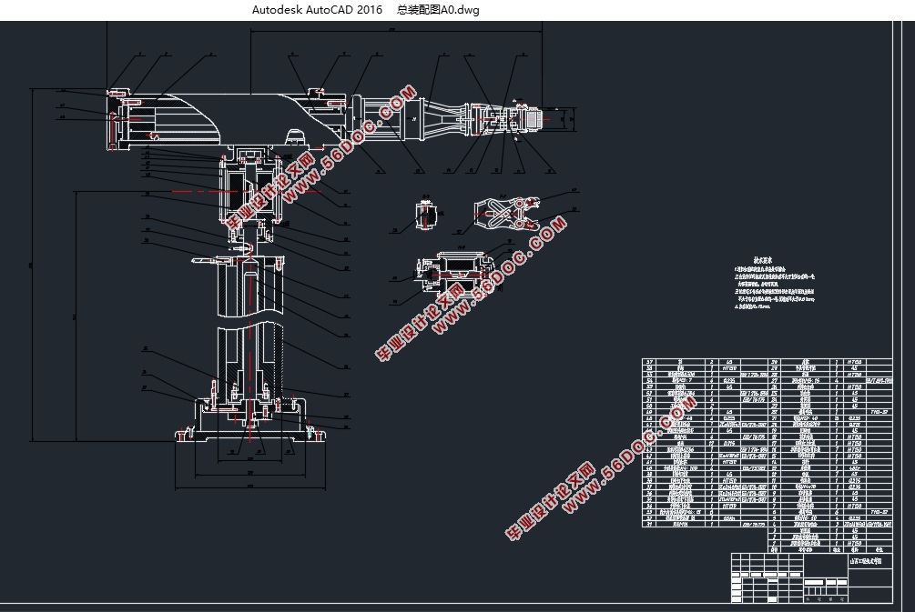
本设计的机械手主要用于配合机床床上下料、搬运等用途;其采用液压驱动、PLC控制、圆柱坐标结构,具有四个自由度,其可分别实现抓取传送带的物料及手腕旋转、手臂旋转、手臂升降及伸缩等功能。本机械手涉及到机械手结构设计、机械手动作的PLC控制设计。结构部分:手爪选用滑槽杠杆驱动机构的二指回转型;手腕及手臂选用回转缸驱动实现回转功能;手臂伸缩和机身升降是通过采用导向杆导向及花键轴导向,确保机械手运动精度;将回转缸置于机身立柱的升降缸上,使结构更紧凑。控制部分:根据机械手的用途,通过编写特定的PLC梯形图程序,实现机械手自动、手动及单周期运转的功能。
本文的设计重点是机械手各个部分液压缸结构尺寸的计算,确定其主要的技术参数;根据本机械手用途,设计特定的PLC梯形图,实现机械手自动、手动及单周期运转功能。并绘制零件设计图、CAD装配图、液压原理图、PLC相关程序。
关键词:机械手;液压驱动;结构设计;PLC控制设计
Structure and Control System Design of Four-DOF Arm
Abstract
With the rapid industrial development, manipulator in machinery manufacturing, assembly and packaging such as the widely used on the automatic production line. Manipulator is a kind of can imitate people part functions, and can according to written procedure for handling materials or grab workpiece, operating tools of device; It play an important role to promote the development of industrial automation production.
The design of the manipulator is mainly used in matching machine tool bed up-down material, handling purposes; The PLC control, hydraulic drive, cylindrical coordinates structure, has four degrees of freedom, the materials can be realized respectively the scraping of the conveyor belt and wrist rotation, rotating, lifting and telescopic arm, and other functions. This involves the manipulator structure design, mechanical movement of manipulator PLC control design. Structural parts: hand claw choose chute lever is held back to drive mechanism transformation; Wrist and arm choose rotary cylinder driven rotary functions; Arm scaling and fuselage lift is by means of guide bar and spline shaft guidance, to ensure that the manipulator movement accuracy; Puts the rotary cylinder fuselage pillar lift cylinder, make the structure more compact. Control part: according to the purpose of the manipulator, by writing specific ladder diagram procedure of PLC, realize the manipulator automatic, manual and the function of the single cycle operation.
This article focuses on the design of the manipulator parts hydraulic cylinder structure size calculation, determine the main technical parameters; Specific purposes, according to the manipulator design of PLC ladder diagram, realize the manipulator automatic, manual and single cycle operation function. And draw parts design, CAD assembly, hydraulic principle diagram, three-dimensional modeling, simulation and PLC programs.
Key words: manipulator; Hydraulic drive; Structure design; PLC control design

目 录
摘 要 i
Abstract. ii
1 绪论 1
1.1 机械手的概述 1
1.2 机械手的历史背景及其现状 1
1.3 机械手的运用及发展趋势 2
1.3.1机械手运用意义 2
1.3.2 PLC在机械手中的应用 2
1.3.3机械手的发展趋势 2
1.4 机械手的工作原理 3
1.5 本机械手的组成 3
1.5.1控制系统 3
1.5.2驱动系统 3
1.5.3执行系统 4
1.5.4位置检测装置 4
1.6 本设计目的及研究内容 4
1.6.1本设计目的 4
1.6.2本设计主要研究内容 5
2 四自由度机械手臂的结构及控制系统总方案设计 6
2.1 设计技术要求 6
2.2 机械手的运动分析 6
2.3 方案拟定 6
2.3.1执行机构方案 7
2.3.2驱动机构方案 7
2.3.3控制方案 8
3 手部设计及计算校核 9
3.1 机械手部设计要求 9
3.2 手部设计方案制定 9
3.3 手部的设计及计算校核 10
3.3.1 驱动力及夹紧力的计算 10
3.3.2 确定液压缸直径D设计尺寸 11
3.4 机械手手爪夹持精度分析及计算 12
3.4.1手爪夹持精度分析 12
3.4.2手爪夹持精度计算 12
4 手腕设计及其计算校核 14
4.1 手腕设计要求 14
4.2 手腕设计方案的制定 14
4.3 腕部转动所需动力矩计算 14
4.3.1驱动力矩计算 14
4.4 确定腕部液压缸直径D设计尺寸 15
4.5端盖连接方式强度计算 15
4.6 动片与输出轴连接螺钉计算 17
5 手臂设计及计算校核 18
5.1 机械手手臂的设计要求 18
5.2 手臂设计方案的制定 18
5.3 手臂设计及计算校核 18
5.3.1手臂驱动力的计算 18
5.4 手臂液压缸的工作压力及结构设计 20
5.4.1确定液压缸工作压力 20
5.4.2确定液压缸的尺寸 20
5.4.3活塞杆的计算及校核 21
5.4.4计算液压缸缸筒长度 22
5.4.5端盖连接方式强度计算 23
6 机身设计及其计算校核 24
6.1 机手机身的设计要求 24
6.2 机身的设计方案制定 24
6.3 机身的设计及计算校核 25
(1)总重量的估算: 25
(2)计算中心与回转轴线之间的距离: 25
(3)摩擦力的计算: 26
(4)惯性力的计算: 26
(5)密封装置的摩擦阻力计算: 26
6.4 升降液压缸的工作压力及结构设计 26
6.4.1液压缸工作压力的确定 26
6.4.2液压缸尺寸的确定 26
6.4.3液压缸外径的确定 26
6.4.4活塞杆的计算校核 27
6.4.5 液压缸缸筒长度的确定 27
6.4.6缸盖螺钉的计算 27
6.5 升降不自锁条件分析计算 27
6.6 回转机构的工作压力及计算 27
6.7 回转缸尺寸的确定 29
6.7.1回转缸油腔内径计算 29
6.7.2回转液压缸缸盖螺钉尺寸的确定 29
6.8 动片与输出轴之间的连接螺钉的计算 29
7 机械手液压系统 31
7.1 机械手液压系统原理图设计 31
7.2液压元件明细表 32
8 机械手动作PLC控制设计 33
8.1 可编程控制器(PLC)介绍 33
8.1.1 PLC的概述 33
8.1.2 PLC的工作原理及基本结构 33
8.1.3机械手PLC型号选择 33
8.2 机械手动作原理及说明 34
8.3 机械手运动动作控制要求 34
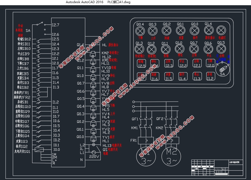
8.4 机械手PLC控制接线图及主电路图设计 35
8.5 机械手操作控制面板设计 35
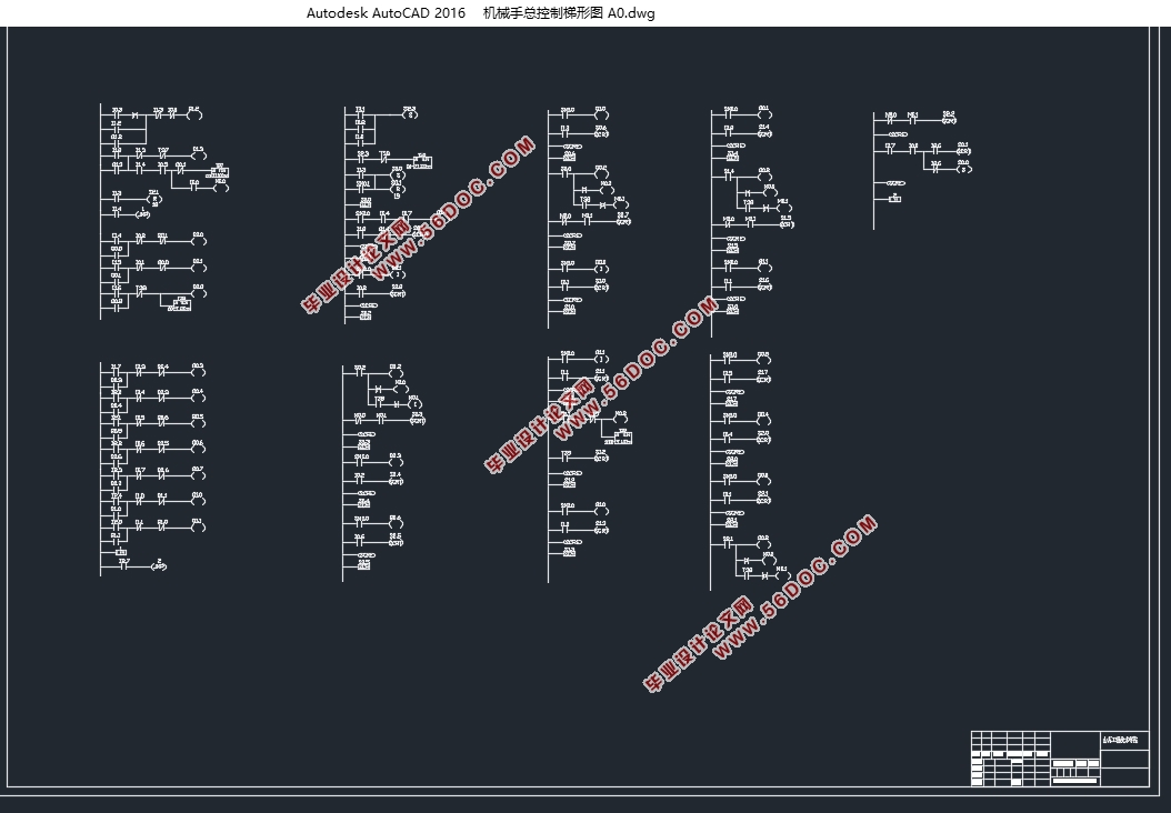
8.6 机械手控制程序设计及说明 36
8.6.1传送带控制程序设计 36
8.6.2传送带的控制及物料检测梯形图说明 38
8.6.3机械手手动控制的控制梯形图 38
8.6.4机械手手动控制梯形图说明 39
8.6.5机械手工作状态转移图及输出梯形图 40
8.6.6机械手工作状态转移图和输入梯形图说明 41
8.7 机械手总控制梯形图(如附录1示意) 43
8.8 机械手总控制指令表(如附录2示意) 43
结论 44
参考文献 45
附录 47
附录1(机械手的总控制梯形图) 47
附录2(指令表) 51
外文文献 53
中文翻译 67
致谢 73
|